Have you ever had replacement parts pass quality inspection with flying colors, only to jam your entire line during setup?
If you are dealing with unexpected downtime and alignment nightmares during packaging line changeovers, the hidden culprit is almost always tolerance stack-up.
In this guide, you will discover exactly how tolerance stack-up affects packaging change-part fit, why individual dimensional accuracy does not guarantee functional fit, and how applying proper GD&T, datum structures, and tolerance analysis eliminates setup hassles for good.
Let's dive right in!
How Tolerance Stack-Up Affects Packaging Change-Part Fit
Precision fit in custom packaging change parts directly impacts overall line productivity. Understanding how minor dimensional variations interact across components is critical to achieving smooth, repeatable container handling.
What Is Tolerance Stack-Up?
Tolerance stack-up is the cumulative combination of individual manufacturing tolerances across an assembly of mating components.
- Manufacturing Tolerance: Every physical part carries an allowable dimensional variation range (± limits).
- Cumulative Accumulation: When multiple components are assembled, these individual variations add together, expanding or contracting the total assembly dimensions beyond single-part specifications.
Why Individual Dimensions Can Pass Inspection but the Assembly Still Does Not Fit
A component can pass quality control on the inspection bench while still failing during installation on the machine.
| Single-Feature Inspection | Total Assembly Reality |
|---|---|
| Measures isolated dimensions against individual 2D drawings. | Combines the worst-case boundary conditions of all mating parts. |
| Verifies individual pin locations, hole diameters, and pockets. | Creates physical interference or excessive play when variations stack in the same direction. |
When adjacent parts reside at their extreme tolerance limits, dimensional variation compromises the mechanical fit, even if every individual part is technically "in spec."
Why Change-Part Fit Matters During Packaging Line Changeovers
An efficient packaging line changeover relies on drop-in, highly repeatable component placement without manual tweaking.
- Eliminates Manual Adjustments: Prevents the need for custom shimming, filing, or forced alignment during setup.
- Protects Container Integrity: Maintains accurate assembly alignment across container-handling zones to eliminate jams, tipping, and bottle scuffing.
- Maximizes Equipment Efficiency: Delivers immediate, predictable line restarts that protect overall production capacity.
Where Tolerance Stack-Up Occurs in Packaging Change Parts
Locating Pins, Dowel Holes, and Mounting Features
Locating pins and dowel holes establish the baseline alignment for every setup. When small variations in pin diameter, hole location, and center-to-center pitch accumulate, change-part fit strays from the nominal position. Clearance fits between pins and mating bushings add micro-movements that skew the entire assembly once fully torqued down.
Starwheels, Feed Screws, and Guide Rail Interfaces
Container transfer depends on tight mechanical fit across consecutive contact points. Dimensional variation on starwheel pockets, feed screw threads, or guide rails shifts container centerlines, leading to line jams during a packaging line changeover. Upgrading to custom precision change parts for packaging machines helps eliminate these combined error paths before they disrupt container movement.
| Interface Component | Tolerance Stack-Up Origin | Operational Impact |
|---|---|---|
| Starwheels | Pocket radius variation + center hub runout | Container pinching and pocket misfeed |
| Feed Screws | Infeed pitch variation + shaft mount clearance | Timing errors at container entry |
| Guide Rails | Bracket mounting play + rail straightness | Variable track width and container tilting |
Change-Part-to-Machine Mounting Relationships
The interface between your change part and the machine frame acts as a major source of stacked errors. Machining tolerances on mounting brackets combine directly with machine-side wear and mounting pad flatness errors. Even if a replacement part matches its drawing specifications, machine-side dimensional variation causes assembly alignment issues upon installation.
Multiple Components Sharing the Same Container Path
When containers pass through sequential packaging change parts along a single transfer track, individual variations accumulate down the line.
- Sequential Shift: A minor offset at the feed screw compounds with rail and starwheel errors, creating a significant deviation by the filling station.
- Track Pinch Points: Stacked variations narrow the container path, causing bottle scuffing, tipping, or sensor misreads.
- Interchangeability Loss: Replacement parts built without accounting for adjacent components create unpredictable fitting issues during changeovers.
- How Tolerance Stack-Up Affects Change-Part Fit and Alignment
Misalignment Between Mating Components
When small manufacturing tolerances build up across multiple packaging change parts, the final mating surfaces rarely sit where the CAD model intended. This cumulative dimensional variation shifts mounting holes, pins, and brackets out of true position. Instead of seamless drop-in assembly, you end up with binding hardware, uneven wear, or parts that require physical force to install. Integrating high-precision custom anodized mounts and brackets maintains rigid datum alignment, ensuring mounting points line up perfectly without distorting adjacent hardware.
Insufficient Clearance or Excessive Play
Accumulated variation pushes the mechanical fit into two destructive extremes:
- Excessive tightness (Zero/Negative Clearance): Parts pinch against one another, causing mechanical binding, excessive friction, and premature component fatigue.
- Excessive play (Loose Fit): Slop between components causes sloshing, vibration, and loss of positioning accuracy during high-speed production runs.
Both outcomes stem directly from failing to calculate total tolerance stack-up during the initial machining and design phases.
Container-Path and Product-Handling Errors
In high-speed packaging lines, container stability depends on exact assembly alignment along the entire transport channel. When guide rails, starwheels, and pockets deviate by even a fraction of a millimeter:
- Bottles and cans tip, misfeed, or jam at feed screws.
- Container walls suffer scuffing or label damage due to incorrect pocket clearances.
- Sensors and filling nozzles miss their precise targeting windows, causing downtime and product waste.
Longer Setup and Adjustment During Changeovers
The primary goal of rapid-change tooling is quick, toolless replacement. However, when poor change part fit forces operators to manually shim, file, or readjust components on the floor, your packaging line changeover window expands significantly. Controlling variation at the manufacturing level eliminates manual tweaking, restoring true drop-in repeatability and maximizing overall equipment effectiveness (OEE).
- A Simple Example of Tolerance Stack-Up
To understand how tolerance stack-up impacts a packaging line changeover, consider how multiple features interact on a single assembly. A change part rarely sits on a machine frame in isolation. Its final physical position relies on a chain of machined surfaces, pins, and mounting brackets, where each feature introduces its own tiny degree of dimensional variation.
Three Dimensions Controlling a Change-Part Location
Imagine a starwheel assembly where the final pocket position depends on three consecutive features:
Machine Base Pocket Offset: Machined with a tolerance of ±0.05 mm.
Mounting Bracket Thickness: Fabricated with a tolerance of ±0.08 mm.
Locating Pin Centerline: Positioned with a tolerance of ±0.05 mm.
Each individual dimension stays well within standard limits. However, understanding how these variations chain together is similar to managing tolerance stack-up in mechanical assemblies, where every component in the chain directly alters the final center point.
How Small Dimensional Variations Accumulate
When we stack these three features together, the variation adds up quickly:
| Component Feature | Nominal Dimension | Individual Tolerance | Worst-Case Shift |
|---|---|---|---|
| Base Pocket Offset | 50.00 mm | ±0.05 mm | +0.05 mm |
| Mounting Bracket | 25.00 mm | ±0.08 mm | +0.08 mm |
| Locating Pin Center | 15.00 mm | ±0.05 mm | +0.05 mm |
| Total Assembly Location | 90.00 mm | Cumulative Range | +0.18 mm Shift |
A total deviation of 0.18 mm might sound small, but in high-speed container handling, a shift over 0.15 mm is enough to cause container scuffing, misfeeds, or constant bottle jams.
Why Nominal Dimensions Alone Do Not Describe Assembly Behavior
3D CAD models show perfect geometry based on nominal dimensions. In reality, no manufacturing process produces exact nominal sizes every time. If we only design for perfect nominal numbers, we ignore real-world manufacturing tolerance. When all parts trend toward their maximum material condition at the same time, the physical packaging change parts will fail to line up correctly on the plant floor despite perfect 3D models.
Functional Fit vs. Individual Feature Accuracy
A component can pass Quality Control with flying colors when measured item-by-item on a bench, yet still cause total line shutdown.
- Individual Feature Accuracy: Confirms that a single hole, slot, or thickness meets its specific print dimension.
- Functional Fit: Guarantees that when all locating features and mating parts bolt together, the overall assembly achieves true datum alignment and smooth container transfer.
Focusing on total functional fit rather than isolated feature tolerances keeps your replacement parts fully interchangeable without manual shimming or custom tweaking.
Methods Used to Evaluate Tolerance Stack-Up
Evaluating how dimensional variation accumulates across mating packaging change parts requires selecting the right calculation model. We rely on proven tolerance stack-up analysis methods to predict physical fit, balance manufacturing costs, and eliminate unexpected misalignment during line changeovers.
Worst-Case Tolerance Analysis
Worst-case tolerance analysis assumes every individual feature is manufactured at its extreme upper or lower tolerance limit simultaneously.
- Guaranteed Interchangeability: Guarantees that parts will always fit, regardless of component variation.
- Conservative Limits: Often results in overly tight manufacturing tolerances, unnecessarily driving up machining costs.
- Best Application: Simple assemblies with low component counts or high-precision setups such as filling nozzle tolerances requiring 5-micron precision.
Statistical Root-Sum-Square (RSS) Analysis
Statistical Root-Sum-Square (RSS) analysis calculates stack-up based on the probability that not all dimensions in an assembly will reach their extreme limits at the same time. It assumes a standard normal distribution centered on nominal values.
- Realistic Thresholds: Yields wider, more achievable tolerances for individual components while maintaining overall mechanical fit.
- Cost Efficiency: Reduces scrap rates and machining cycles by avoiding unnecessarily tight limits on non-critical features.
- Controlled Risk: Accepts a minimal statistical probability of tight fits, making it standard practice for production packaging change parts.
When More Advanced Statistical or Monte Carlo Analysis May Be Useful
Standard RSS falls short when packaging change-part fit involves 3D spatial alignments, non-linear kinematic links, or non-normal distribution patterns. Monte Carlo simulations run thousands of randomized dimensional iterations to model real-world assembly behavior.
- Non-Linear Mechanical Assemblies: Essential when container paths depend on angular rotation, cam profiles, or complex guide surfaces.
- High-Speed Tooling Verification: Predicts performance before committing to complex, multi-axis machining.
- Variable Operating Conditions: Helps model thermal expansion and material deflection in demanding production environments.
Why the Appropriate Method Depends on the Assembly and Production Requirements
Selecting the right evaluation technique requires balancing functional criticality, assembly complexity, and manufacturing cost.
| Analysis Method | Core Calculation Basis | Ideal Application | Manufacturing Impact |
|---|---|---|---|
| Worst-Case | Extreme dimensional limits combined | Simple 2D stacks, critical safety interfaces | Higher machining costs, zero assembly fit risk |
| RSS Statistical | Square root of summed squared tolerances | Multi-part linear assemblies, standard mounting | Balanced production costs, minimal statistical risk |
| Monte Carlo | Statistical computer simulations | 3D complex paths, non-linear packaging drives | Optimized machining tolerances, highly predictable yields |
- How Datums and GD&T Help Control Assembly Variation
Standard plus-minus (+/-) tolerances often fail in complex packaging assemblies because they let dimensional variation accumulate across every feature edge. We use Geometric Dimensioning and Tolerancing (GD&T) to define parts based on how they physically interface on your production line, keeping tolerance stack-up under strict control.
| Tolerance Control Method | How Variation Accumulates | Impact on Packaging Change Parts |
|---|---|---|
| Standard ± Tolerances | Linear addition across every individual feature | High risk of binding, misalignment, and manual tweaking |
| GD&T Datum System | Fixed reference points based on real functional fit | Predictable assembly alignment and true drop-in interchangeability |
Establishing Functional Datum References
We establish functional datums that directly reflect your machine's actual mounting surfaces. Instead of measuring from an arbitrary machined edge, dimensions are tied directly to the primary locating pins, shafts, and mounting faces.
Locking in these real-world contact points ensures every replacement part seats consistently. Understanding how GD&T controls locator plate repeatability is essential when manufacturing parts that must lock into position on the line without constant re-zeroing.
Position Tolerance for Locating and Mounting Features
Position tolerances define the exact zone where a hole or pin center must lie, stopping location errors from drifting out of spec across mating interfaces.
- True Position Control: Holds dowel pin and bolt hole locations precisely relative to the main mounting grid.
- Clearance Guarantees: Ensures male and female mounting hardware line up cleanly without forced insertion or filing.
- Bonus Tolerance: Provides extra manufacturing flexibility when features are produced away from Maximum Material Condition (MMC) without compromising change part fit.
Controlling Feature Relationships Instead of Only ± Dimensions
Standard ± dimensions treat every feature as an isolated measurement. GD&T controls how critical features relate to one another geometrically, protecting the mechanical fit.
- Parallelism & Perpendicularity: Prevents tilted guide rails that pinch containers along the transfer path.
- Concentricity & Coaxiality: Maintains precise centerline alignment between starwheels, pocket inserts, and center guides.
- Orientation Control: Eliminates angular twisting across long, multi-segment guide assemblies.
Managing Tolerance Stack-Up Across Mating Components
Controlling individual parts is only half the job; the ultimate goal is system-level repeatability. By applying a unified GD&T datum structure across all mating change parts, we compress the total manufacturing tolerance stack. This systematic approach eliminates trial-and-error adjustments and guarantees seamless performance during every packaging line changeover.
Manufacturing Factors That Affect Change-Part Fit
Manufacturing precision directly determines whether individual component tolerances work together or cause assembly failure on the line. Small variations during production quickly accumulate, compromising overall change part fit.
CNC Machining Accuracy and Process Capability
Machine tool precision sets the baseline for dimensional variation. A machine operating near its limits produces wider tolerance spreads across batch runs, compounding errors when parts hit assembly.
- Machine Drift and Tool Wear: Spindle thermal expansion and cutting tool wear alter critical dimensions over long production cycles.
- Axis Positioning: Complex change parts require high positioning accuracy. Utilizing advanced cam profile machining with 5-axis setups eliminates multi-setup stack-ups by finishing complex geometries in a single operation.
- Process Capability ($C_{pk}$): High process capability ensures dimensions stay tightly clustered around nominal values rather than drifting toward tolerance limits.
Workholding and Datum Transfer Between Machining Operations
Re-clamping a part across multiple operations introduces reference errors that directly disrupt datum alignment.
- Datum Shifts: Switching workholding fixtures between operations shifts your reference point, creating positional errors on locating features.
- Clamping Pressure: Excessive fixture pressure deforms the part during cutting. Once released, the part relaxes into an out-of-spec geometry.
- Single-Setup Machining: Holding key locating points and functional surfaces in the same fixture guarantees precise spatial relationships across the component.
Material Distortion and Thermal Effects
Raw material behavior under heat and mechanical stress impacts final assembly alignment.
| Factor | Primary Mechanism | Impact on Tolerance Stack-Up |
|---|---|---|
| Residual Stress | Machining releases internal stresses in extruded plastics or cold-rolled metals. | Parts warp or twist after removal from the fixture. |
| Thermal Expansion | Ambient shop temperature changes expand or contract materials during cutting. | Dimensions shift when parts cool down to standard operating temperatures. |
| Material Stability | Polymers like Delrin or UHMW-PE absorb moisture and expand over time. | Tight-clearance fits seize up or bind inside the packaging machine environment. |
Surface Finishing and Its Effect on Critical Dimensions
Post-machining surface treatments add or remove material, altering tightly controlled manufacturing tolerance bands if not calculated in advance.
- Plating and Anodizing Layer Thickness: Hard-coat anodizing or nickel plating adds measurable thickness to pin diameters, bores, and mounting faces.
- Abrasive Finishing: Bead blasting and manual polishing can unevenly erode sharp edges, radii, and reference surfaces.
- Pre-Finish Machining Adjustments: Critical mating dimensions must be undercut or overcut before plating to ensure the final finished part meets exact fit specifications.
processing
How to Improve Replacement Change-Part Interchangeability
Swapping out worn components on a packaging line shouldn't turn into an hours-long troubleshooting session. To ensure smooth packaging line changeovers, replacement packaging change parts must drop directly into place without manual shimming or filing. We focus on a few key engineering practices to eliminate tolerance stack-up issues and guarantee drop-in interchangeability.
Use the Same Functional Datum Structure as the Original Design
Maintaining precise change part fit requires aligning replacement parts to the exact same physical datums used by OEM components.
- Maintain Zero-Point References: Always reference machining from the primary locating features rather than cosmetic outer edges.
- Match Machine Baselines: Align dowel holes, slot centers, and mounting faces to identical reference points to prevent dimensional variation.
- Preserve Datum Alignment: Consistent datum alignment ensures that minor manufacturing tolerances don't shift container pockets off-center.
Identify Critical-to-Fit Dimensions and Interfaces
Not every surface on a component requires micro-inch accuracy. We isolate the true critical-to-fit features to manage tolerance stack-up analysis effectively.
| Feature Type | Key Areas | Required Precision Strategy |
|---|---|---|
| Locating Interfaces | Pin holes, mounting slots, shaft bores | Tight positional tolerances to lock down mechanical fit |
| Product Contact Zones | Starwheel pockets, guide rails, pocket curves | Controlled profile tolerances for smooth container flow |
| Clearance Zones | Outer chamfers, relief pockets | Standard manufacturing tolerances to cut unnecessary cost |
Focusing precision on critical interfaces—like we do when manufacturing custom CF30 PEEK wear parts for food conveyors—guarantees perfect assembly alignment without forcing unnecessary costs onto non-mating surfaces.
Avoid Unnecessarily Tight Tolerances on Non-Critical Features
Over-specifying tolerances across an entire drawing is a common mistake that actually increases the risk of part rejection and assembly alignment problems.
- Prevent Compounding Stack-Up: Tightening non-critical dimensions can force machinists to compromise on primary functional datums.
- Control Cost and Lead Time: Focus tight tolerances strictly where mechanical fit matters to keep production efficient.
- Allow Natural Relief: Standardize non-mating dimensions to give mating features room to self-align naturally.
Control Batch Consistency for Multiple Replacement Parts
When ordering replacement parts in sets, every part in the production run must perform identically to prevent line adjustments between setups.
- Fixed Workholding & Tooling: Use rigid, repeatable CNC fixtures to maintain tight process capabilities across entire batches.
- Material Batch Verification: Verify raw material thermal stability and stress relief before final machining to prevent warping.
- In-Process Statistical Checks: Track key dimensions throughout production to eliminate batch-level drift before parts ship to your line.
Inspection Strategies for Tolerance-Critical Change Parts
Catching dimensional variation before parts hit your packaging line prevents costly changeover delays and assembly binding. We implement a structured verification routine to ensure every component meets exact geometric requirements before installation.
Inspecting Critical Dimensions and Locating Features
We prioritize features that directly dictate how a part mounts and interfaces with the machine frame:
- Locating Pins and Dowel Holes: Verified for hole size, center-to-center distance, and perpendicularity to maintain precise mounting alignment.
- Guide Rail Profiles and Starwheel Pockets: Checked for contour consistency to ensure smooth container transfer without pinching.
- Mounting Faces: Measured for flatness to prevent rocking or secondary tilt across the assembly.
CMM Verification of Datum and Position Relationships
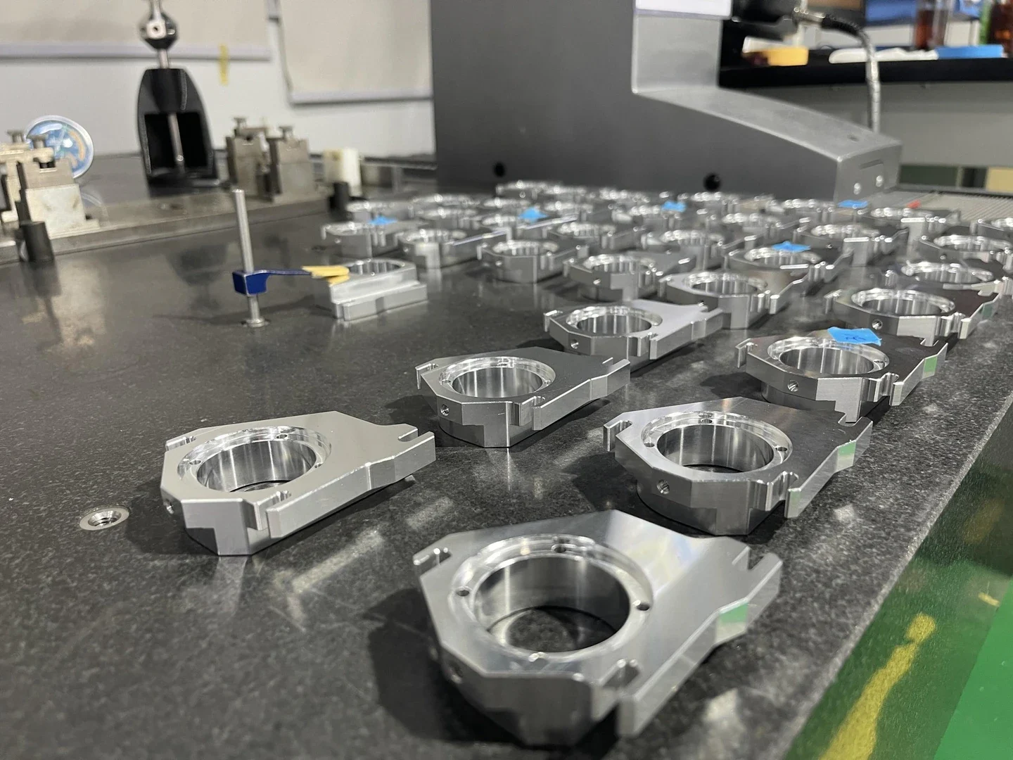
To control true position tolerances across complex shapes, coordinate measuring machines (CMM) provide accurate 3D dimensional verification. Our rigorous quality inspection capabilities ensure every datum structure matches the master CAD model precisely.
| Inspection Method | Target Features | Primary Benefit |
|---|---|---|
| Hand Metrology (Calipers/Micrometers) | Outer dimensions, pocket widths, plate thickness | Fast shop-floor checking of basic features |
| CMM Inspection | Datum references, true position, hole pattern pitch | High-precision verification of complex spatial relationships |
| Optical / Vision Systems | Form radii, edge chamfers, smooth transitions | Non-contact measurement for delicate or flexible components |
Functional Inspection of Mating Features When Appropriate
Static dimensional checks do not always reflect real-world mechanical fit. Whenever possible, we conduct functional inspections using master fixtures or mating components:
- Go/No-Go Gaging: Rapidly checks pin clearances and slot spacing on critical interfaces.
- Fixture Mock-Up Testing: Simulates line installation to guarantee effortless clamping and drop-in fit.
- Container Path Traversal: Manually passes sample containers through assembled starwheels and guide rails to confirm correct operating play.
Using Inspection Reports for Repeat Production
Detailed inspection reports serve as the permanent dimensional baseline for reorders. Archiving critical CMM data and first-article reports guarantees that replacement packaging change parts maintain full interchangeability over time, eliminating tolerance stack-up issues during future packaging line changeovers.
What to Provide When Ordering Precision Packaging Change Parts
To eliminate costly tolerance stack-up issues and guarantee a seamless change part fit on your production line, precise technical data is required during the ordering process. Providing complete manufacturing specifications upfront ensures replacement packaging change parts drop into position without manual tweaking or downtime.
Complete 2D Drawings and 3D CAD Models
- 3D CAD Files (.STEP / .IGES): Essential for accurately capturing complex surface geometries, pocket profiles, and curved container paths.
- Fully Dimensioned 2D Drawings (.PDF): Crucial for defining linear tolerances, geometric tolerances, thread specifications, and surface roughness requirements that 3D models do not communicate on their own.
Critical Fits, Datums, and Mating Component Information
Establishing functional datums prevents cumulative dimensional variation across multi-part assemblies:
- Clearly identify primary, secondary, and tertiary datum features used for mounting and locating.
- Detail critical mounting interfaces, such as locating pin hole locations, slot fits, and precision locator plates for packaging machine assemblies.
- Share information on adjacent mating hardware to preserve proper assembly alignment across the entire container line.
Material, Surface Finish, and Operating Requirements
Operating conditions dictate exact material selections and finishing standards to prevent binding, wear, or container damage:
- Material Specs: State exact material grades (e.g., UHMW-PE, PET-P, 304/316L stainless steel, or anodized aluminum). Evaluating hard-anodized aluminum vs 316L stainless packaging parts helps balance weight, corrosion resistance, and structural strength.
- Surface Finish: Define maximum Ra surface roughness values for container-contact pockets and guide rails to ensure smooth bottle flow during high-speed packaging line changeover.
- Environment: Note washdown chemical exposure, operating temperatures, and line speeds.
Quantity and Inspection Documentation Requirements
Specify order volumes and exact quality control deliverables to verify functional mechanical fit prior to installation:
- Production Quantities: Indicate whether parts are for single replacement units or synchronized multi-lane sets to maintain batch-to-batch consistency.
- Quality Reports: Request First Article Inspection (FAI) reports, CMM measurement data, or Certificates of Conformance (CoC) for critical dimensions.
| Order Package Element | Key Items Included | Purpose & Impact |
|---|---|---|
| CAD & Drawings | 3D models (.STEP) + 2D dimensioned PDFs | Prevents geometry errors and establishes true tolerance bounds |
| Datum Schemes | Functional datums, GD&T position specs | Controls tolerance stack-up analysis outcomes and locator fit |
| Material & Surface Specs | Material grade, coating, Ra roughness | Ensures chemical resistance, low friction, and long wear life |
| Inspection Requirements | CMM measurement reports, FAI, Material CoC | Guarantees interchangeability without machine modification |