
Drawing-Based Surface Finishing for Packaging & Processing Machinery Parts
Define treated areas, edge acceptance, final dimensions and surface texture. Our Wuxi machining base focuses on CNC milling and turning; extra finishing processes require separate confirmation.
Specialized Substrates
Specify exact material grade, condition and required documents for stainless steel, polymers or aluminum.
Controllable Roughness
Specify texture parameters, limits and checking locations; roughness alone does not establish cleanability.
Machining and Finishing Route Review
CNC milling and turning in Wuxi, with no in-house 5-axis, EDM or wire-cutting equipment. Secondary processes are confirmed for the part.
Shanghai Zhansong Industry Co., Ltd. / ZSCNC reviews drawing-based components. Machining, additional finishing, inspection and document requirements are confirmed before order acceptance.
Deburring and Edge Treatment Requirements for Food Machinery Parts
Specify edge breaks, permitted burr condition, critical interfaces and checking access. Any deburring method and final-dimensional acceptance must be agreed for the geometry. These requirements matter for the food processing industry, where the equipment designer validates cleaning and operating performance. We also review machine parts programs against the approved edge and fit requirements.
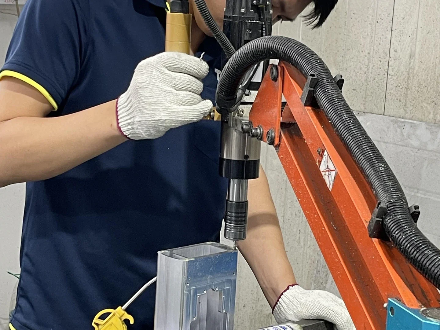
In-Process Edge Inspection and Tolerance Verification
Our Standardized Edge Conditioning Workflow
- 1Drawing & IQC Review:Our process engineers thoroughly evaluate your design files, isolating sensitive mating surfaces and explicitly mapped edge radii to determine the optimal finishing path.
- 2Post-Machining Audit:Immediately following CNC milling or turning, parts undergo a preliminary inspection to map out burr density, cross-hole flashing, and concentrated sharp areas.
- 3Precision Deburring Execution:Agree the deburring method, permitted material removal, access and final dimensional acceptance for each feature.
- 4Dual-Stage Verification:Agree which features require individual-part inspection or sampling, the measurement method and report. No zero-defect or complete optical inspection guarantee is implied.
Drawing-Based Process Review
Review internal intersections and critical edges before confirming a route. Deburring can affect dimensions and access; finishing alone does not establish safety or compliance.
- Hybrid Deburring MethodsManual or mechanical methods may be proposed where suitable. Access to blind holes, threads and internal features must be reviewed, and the route confirmed before acceptance.
- Component-Specific Edge OptimizationThe approved drawing defines edge breaks, sealing areas, dimensions and allowed finishing. Changes require customer approval.
- Tight Dimensional & Tolerance ControlConfirm permitted material removal and check specified final dimensions after the agreed finishing steps.
- Material and Substrate ProtectionMaterial grade, finish and appearance acceptance must be specified. A process name does not guarantee freedom from scratches or surface damage.
- Custom Chamfers and Micro-RadiiInspect approved chamfers or radii at agreed locations; film handling, assembly and operator safety require equipment-level validation.
RFQ Tip: Specify the required edge break, critical interfaces and burr acceptance. Vague notes such as "No Sharp Edges" may require clarification. Specify edge breaks, critical interfaces and burr acceptance clearly. Resolve ambiguous notes before order acceptance.
View typical machine parts case studies for knife holders and cutting assembliesMechanical Polishing and Surface Roughness Control
Specify final dimensions and texture limits at the relevant functional areas. For
Surface finish is one component of equipment design and cleaning validation. A polish name or low Ra does not by itself establish CIP/SIP compatibility or hygienic certification.beverage-processing industry, where cleaning and operating performance need application validation.
Surface Texture Specification Guide
- Measurement Requirements:Agree the surface-texture parameter, locations, equipment access, inspection frequency and report. Profilometer measurement is not included by default.
- Zone-Specific Finishes:Identify contact areas, sealing or sliding interfaces and appearance requirements separately. The designer defines the appropriate acceptance limits.
- Specified Stainless Steel Finish:Define the required final dimensions and surface texture for stainless parts. Polishing allowance and critical geometry must be reviewed before production.
Mark final-size dimensions and texture checking locations on the drawing. Feasibility and reporting are confirmed before acceptance. Mark texture parameters, checking locations and final-size dimensions. Feasibility and reporting are confirmed for the actual geometry.
Stainless Steel Mirror Polishing
Ideal For: Sanitary environments requiring high cleanability.
Specify the target texture, treated areas and appearance. A mirror finish does not establish non-stick, cleaning-cycle or contamination-prevention performance.
Industrial Brushed Finish
Ideal For: Machine exteriors, structural frames, and safety enclosures.
Specify brushing direction, appearance acceptance, treated areas and final dimensions. Corrosion suitability depends on material and environment.
Functional & Polymer Polish
Ideal For: Low-friction slide tracks and mechanical wear parts.
Tailored specifically for engineering polymers like PEEK, POM, and UHMW-PE, as well as specialized alloys. This is especially valuable for custom machine parts that need stable motion and low wear. We optimize the surface texture to control friction coefficients, preventing part wear and eliminating material particulate shedding.
Integrated CNC and Finishing Workflow
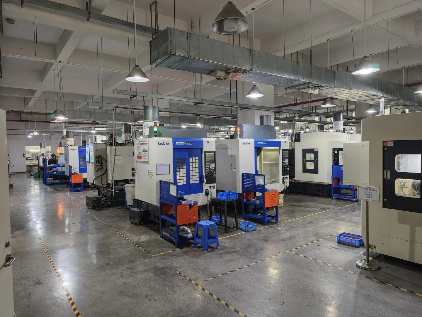
Review machining, finishing and inspection as an agreed route. Extra processes may require separate arrangements; no complete in-house finishing capability is assumed.
Design Review: Surface & Tolerance Analysis
Every project begins with an intensive blueprint evaluation. Our engineers analyze the required surface roughness, functional zones, and geometry to optimize the manufacturing sequence. We establish clear manufacturing baselines before production starts.
CNC Machining: Shape & Dimension
Our Wuxi base focuses on CNC milling and turning, with no in-house 5-axis, EDM or wire-cutting equipment. Confirm any additional route and final acceptance after finishing.
Inspection: Burrs & Critical Features
Specify accessible cross-hole intersections, edges and critical features. Agree checking method and burr acceptance before manufacture.
Deburring / Pre-Polish: Manual or Mechanical
Agree deburring or pre-polishing methods and material-removal limits for the critical geometry.
Polishing: Achieve Target Finish
Requested polishing, brushing or buffing routes and inspection requirements must be confirmed for the part.
Cleaning: Remove Residues
Specify cleaning requirements and acceptance evidence. A cleaned component is not automatically sterile; ultrasonic or chemical cleaning is not assumed to be included.
QA: Dimensional & Roughness Check
Inspect the agreed dimensions and surface characteristics after finishing. Measurement method, access, frequency and records are confirmed by order.
Surface Acceptance and Application Validation
For product-contact or critical interfaces, specify the application requirements, treated areas, texture and final dimensions. Cleaning and regulatory compliance require application validation.
Drawing and Order Requirements
- Customer-Specified MaterialsSpecify exact grade, condition and required records. Material names do not establish food-contact, FDA or other regulatory compliance.
- Approved Drawing GeometryMachine the approved geometry. Drainage, cleaning and CIP/SIP performance require validation of the complete equipment.
- Traceable Inspection RecordsRequest the specific inspection records and material documents needed. Availability and retention are confirmed before acceptance.
- Agreed Cleaning and PackagingSpecify cleaning and packaging. Additional methods and evidence require confirmation; transport contamination cannot be ruled out by packaging alone.
State the application and required documents for components across related As a trusted supplier to leading Japanese, European, and American food equipment OEMs across related industries. Final equipment hygiene and performance are validated by the equipment owner.
Engineering Guide
Specify your internal factory hygiene standards, target Ra surface roughness specifications, or required regulatory certifications directly within your RFQ documents.
Tailored Surface Finishing for Diverse Food Processing Equipment
Different applications need different material, geometry, edge and finish requirements. Specify these in the drawing and RFQ rather than assuming one sanitary finish suits every component.
Equipment Applications
Drawing-based finishing requests may cover the following equipment applications; suitability and outcomes require equipment validation.
- Flow Wrapping & HFFS SystemsContinuous motion packaging lines demanding ultra-smooth product pathways and perfectly conditioned forming shoulders.
- Filling & Sealing MachinerySpecify contact areas, passages, seal interfaces and the cleaning conditions for filling equipment.
- Cartoning, Boxing & Secondary PackagingSpecify edge acceptance and contact geometry for sorting and case-packing parts.
- Conveying & Material Handling LinesDefine material, texture and contact requirements for transfer and sorting components.
- Dairy, Meat, Bakery & Commercial ProcessingDefine material and surface requirements against the actual cleaning chemicals, temperature and operating conditions.
Components & Key Finishes
Define component-specific edge and texture acceptance. Wear, fatigue and hygiene outcomes require application validation.
Knife Holders & Cutters
Deburring + Functional PolishingInspect approved edges and blade-seating geometry. Clamping, film handling and operator safety are equipment-level checks.
Sealing Jaws & Heat Blocks
Mirror or Low Ra FinishSpecify final texture and dimensions of sealing teeth and plates. Thermal release and material accumulation require process validation.
Guide Rails & Wear Slides
Low-Friction Polishing for PolymersSpecify polymer grade, geometry and texture; friction, wear and particle generation require application validation.
Enclosures, Guards & Framing
Brushed or Satin FinishesSpecify brushing direction, appearance and treated areas. Do not infer corrosion resistance from an appearance finish.
Contact us if your equipment isn't listed
Automated food lines rely on specialized part geometries and proprietary tolerances. Our production and quality control engineers frequently assist OEM designers in establishing ideal deburring sequences, custom chamfers, and precise roughness profiles for complex 2D and 3D CAD models.
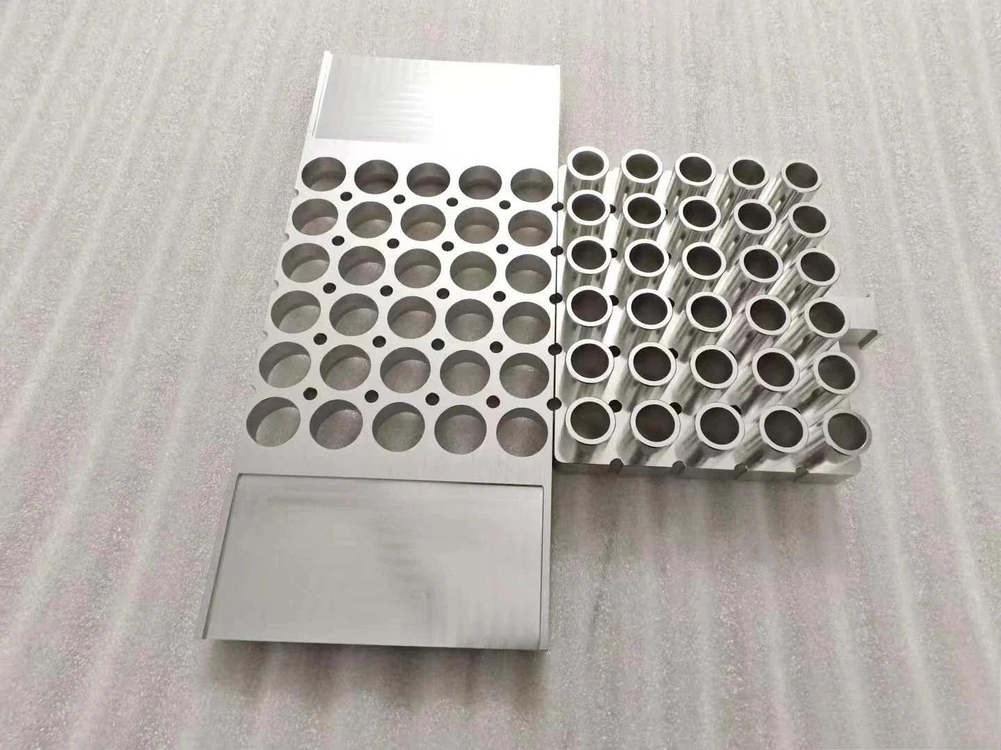
Equipment Application & Component Finishing for Food Machinery Parts
Specify material, edge condition, treated areas and texture for the equipment design. Final-dimension checks and application validation are separate requirements.
Why Choose ZSCNC for Single-Source Processing
For drawing-based components in the ZSCNC integrates surface finishing into your production flow, eliminating secondary vendor handoffs entirely.
Final tolerances, texture, process route and inspection requirements must be agreed before production.
| Capability / Metric | Traditional Machine Shops | Specialized Polishers | ZSCNC Integrated Solution |
|---|---|---|---|
| Process Integration | Confirm Finishing Responsibility | Confirm Machining Responsibility | Route Confirmed by Order |
| Food Industry Experience | Review Relevant Scope | Review Required Finish | Define Application Requirements |
| Quality Records | Specify Records | Specify Report Scope | Records Confirmed by Order |
| Communication | Agree Contact Responsibilities | Agree Technical Scope | Written Order Clarification |
| Total Cost | Confirm Quoted Scope | Confirm Process Costs | Price Confirmed for the Part |
Unified Process Planning
Review material-removal allowance, setup and inspection access before quoting. Check final-size dimensions after the confirmed finishing sequence.
Confirmed Lead Time
Lead time depends on machining, additional processes, material availability and scheduling. It is confirmed for the order.
Part-Specific Cost Review
Cost depends on material, geometry, quantity, finishing and reporting. No fixed savings or lowest-cost guarantee is offered.
Consolidate Your Machining & Finishing Workflow
Streamline your procurement process and protect tight tolerances with our single-source manufacturing.
Surface Roughness and Process Selection Guide
Use the approved design and applicable application requirements to specify surface acceptance. A generic texture range does not establish food safety or equipment cleanability.
Engineering Selection Framework by Zone
The equipment designer defines the product-contact texture and cleaning acceptance for the application.
Recommended Process Combination
- Multi-Stage Mechanical Polishing: Successive grit polishing stages to remove raw CNC tooling marks completely.
- Manual Micro-Fine Refinement: Targeted hand-polishing for complex inner radii, nozzle openings, and sealing grooves.
- Specified Cleaning Route: Agree the required cleaning route and evidence; no sterile or contamination-free delivery is assumed.
Typical Applications: Filling nozzles, flow-diversion valves, manifold blocks, sealing jaw faces, and mixing paddles.
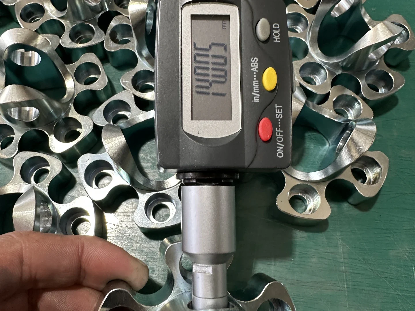
Surface Treatment Review Examples
The following examples describe review questions, not verified customer projects or measured results. The actual route and acceptance must be agreed for each part.
Reviewing Edges on Flow-Wrapping Components
Example Requirement
Illustrative request: review blade-holder or guide edges that may contact packaging film. Obtain approved drawings, mating information and trial observations before proposing a change.
Proposed Review
Proposed review: identify the specified edge break, burr acceptance, contact geometry and critical dimensions. Any geometry or process change needs customer approval.
Validation Needed
Validation needed: the equipment owner checks film handling in the assembled line. Dimensional and edge inspection do not guarantee zero film damage.
Reviewing Filling-Component Surface Requirements
Example Requirement
Illustrative request: review internal passage geometry, texture and cleaning access for a filling component. Provide the actual product and cleaning conditions.
Proposed Review
Proposed review: define treated areas, final-size allowance and the approved surface-texture limit. Any internal-geometry change requires designer approval and cleaning validation.
Validation Needed
Validation needed: cleaning and operating trials for the actual assembly. No faster cycle, reduced chemical use, audit pass or risk-free operation is promised.
Continuous Quality Optimization
Report deviations with drawing revision, affected quantity and evidence. Agree corrective action and follow-up checks against the confirmed acceptance criteria.
Get Your Parts Finishing Started
Shanghai Zhansong Industry Co., Ltd. / ZSCNC reviews drawing-based machining and separately confirmed finishing requirements. Send the current drawing revision and acceptance criteria for quotation.
Upload for finishing quote
Share CAD files or part photographs for a custom surface treatment proposal.
Prototype to OEM scale
Prototype and batch quantities are quoted separately for the confirmed route.
Specified Finish Targets
Specify texture, treated areas and any requested process; route and inspection need confirmation.
Direct Contact
Please email us to confirm correspondence and meeting arrangements.
Wuxi, Jiangsu, China. Visits by prior confirmed arrangement.
Request and agree any NDA before sharing confidential drawings.