How GD&T Controls Locator Plate Repeatability
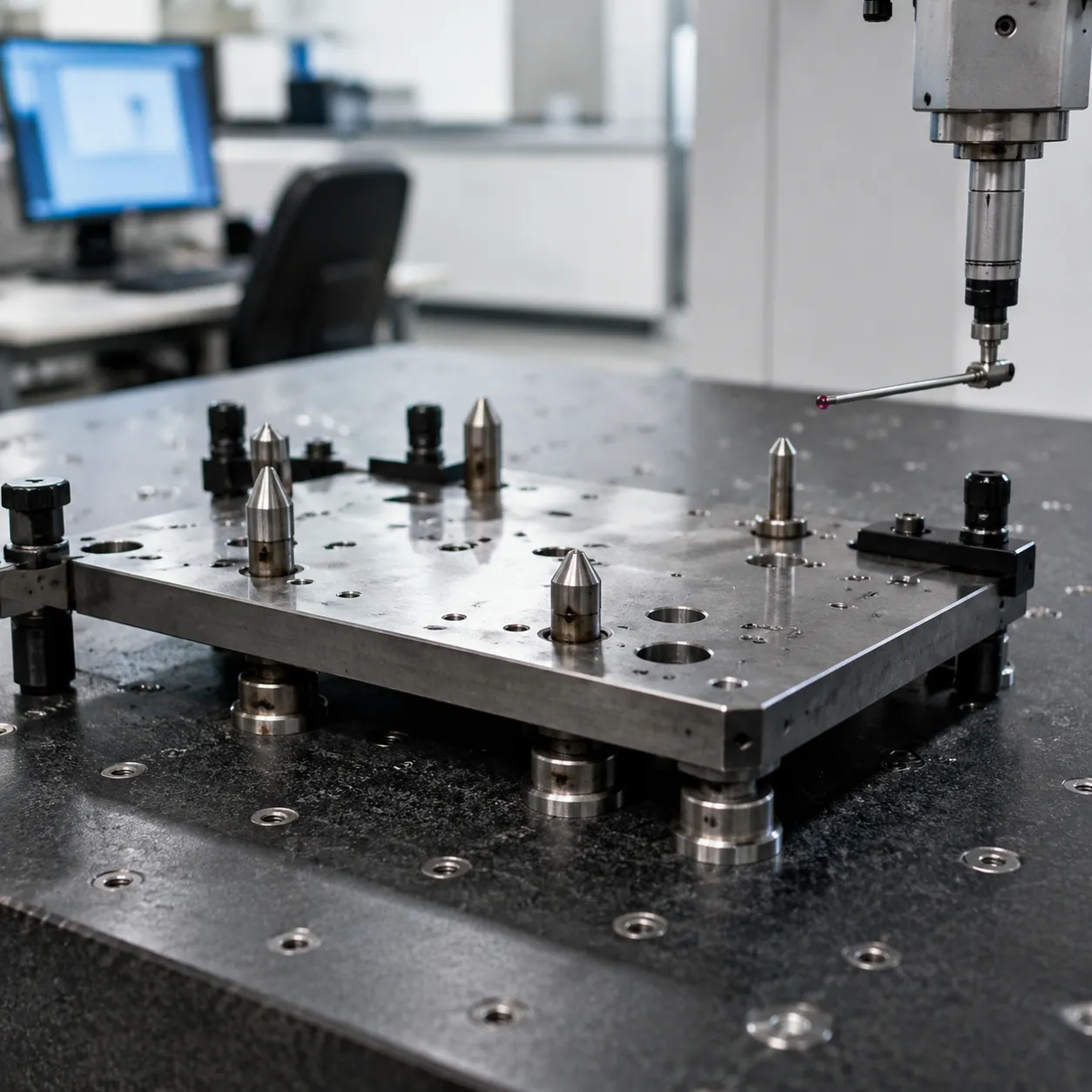
High-precision packaging machinery relies on consistent component positioning to maintain continuous operational speed and product quality. Geometric Dimensioning and Tolerancing (GD&T) provides the mathematical framework required to lock down locator plate repeatability across production runs and maintenance cycles.
Why Repeatability Matters in Packaging Machine Assemblies
In high-speed packaging equipment, a misalignment of even 0.05 mm can disrupt downstream operations. Locator plates position tooling, containers, and sealing units throughout the automated process.
- Downtime Prevention: Inconsistent plate positioning leads to mechanical jams, premature wear on guide rails, and frequent machine stoppages.
- Package Seal Integrity: Precise packaging machine alignment ensures heating elements, cutters, and pick-and-place mechanisms register perfectly with the packaging substrate.
- Seamless Interchangeability: Maintenance technicians can swap worn locator plates directly out of inventory without custom shimming or manual re-alignment.
What GD&T Controls Beyond Basic ± Dimensions
Traditional plus/minus (±) coordinate tolerances define square or rectangular tolerance zones that fail to reflect physical assembly conditions. GD&T replaces these ambiguous limits with functional geometric controls:
- True Position: Replaces square coordinate zones with a cylindrical position tolerance zone, maximizing usable manufacturing tolerance while ensuring strict location control.
- Form and Orientation: Controls critical surface parameters like flatness, parallelism, and perpendicularity independently of feature size.
- Functional Boundary: Establishes precise limits for locating pin tolerance and mounting hole patterns, guaranteeing virtual condition fit during final assembly.
How GD&T Reduces Manufacturing and Inspection Ambiguity
Standard linear dimensions leave the origin of measurement open to interpretation, creating discrepancies between machining setups and quality verification. GD&T eliminates this uncertainty by establishing a unified reference system.
- Standardized Reference: Establishes fixed physical contact points that mirror actual assembly mating conditions.
- Unified Protocols: Ensures machinists, tooling builders, and quality control teams measure features from identical baseline surfaces.
- Objective Verification: Streamlines CMM inspection by defining clear mathematical rules for feature evaluation, eliminating disagreement over part acceptance.
Building a Datum Reference Frame for a Locator Plate
Establishing a robust Datum Reference Frame (DRF) is the foundation of controlling locator plate repeatability. By locking down all six degrees of freedom, we eliminate setup variability during both manufacturing and packaging machine assembly.
Primary, Secondary, and Tertiary Datums
A complete DRF uses three mutually perpendicular planes derived from actual physical features on the part.
| Datum Order | Physical Feature Type | Degrees of Freedom Constrained | Functional Role |
|---|---|---|---|
| Primary (A) | Large Flat Base Surface | 3 (1 Translation, 2 Rotations) | Establishes main mounting plane and orientation |
| Secondary (B) | Precision Edge or Pin Centerline | 2 (1 Translation, 1 Rotation) | Controls directional alignment and orientation |
| Tertiary (C) | End Surface or Secondary Hole | 1 (1 Translation) | Fixes final location along the remaining axis |
How the 3-2-1 Locating Principle Relates to Datum Establishment
The 3-2-1 principle directly dictates how we establish the DRF on a machining fixture or CMM setup:
- 3 Contact Points (Primary): Three contact points on the bottom face define a stable plane, preventing vertical displacement and tilt across two axes.
- 2 Contact Points (Secondary): Two contact points along a reference edge or dowel line create an alignment axis, stopping in-plane rotation.
- 1 Contact Point (Tertiary): A single point on an end stop locks the final translational axis.
Matching this physical constraint method on the engineering drawing guarantees that inspection setups mimic real-world machine mounting.
Choosing Functional Datum Features on a Locator Plate
Functional datum selection means picking features that physically interface with the host machine setup:
- Mounting Face: Always select the primary mating face as Datum A to control planarity and surface contact.
- Primary Dowel Hole: Select the primary locating pin hole as Datum B rather than raw, unmachined outer plate edges.
- Secondary Slot or Hole: Use a secondary dowel slot as Datum C to control rotation without over-constraining the plate.
When manufacturing our precision locator plates for packaging machine assemblies, aligning drawing datums directly with physical mounting surfaces keeps tolerance stack-ups minimal.
How Datum Selection Supports Repeatable Assembly Alignment
Correct datum alignment allows replacement plates to drop straight into machine frames without requiring manual fitting, grinding, or shimming.
- Eliminates Inspection Drift: Machinists and quality control inspectors measure every feature from the exact same structural baseline.
- Locks True Position: Critical pocket locations and indexing pins match their mating components every single time.
- Accelerates Maintenance: Field technicians swap out worn plates in minutes while preserving original line timing and registration.
- Which GD&T Controls Matter Most on Locator Plates?
We rely on targeted geometric controls to lock down critical alignment features on every locator plate. Standard plus-minus dimensions fall short when securing repeatable positioning, making specific locator plate GD&T callouts essential for high-performance packaging assemblies.
| GD&T Control Symbol | Target Feature | Core Functional Purpose |
|---|---|---|
| Position Tolerance | Dowel holes, bolt patterns | Controls true center location within a cylindrical zone |
| Flatness | Primary seating base | Eliminates rock and bow without requiring a datum reference |
| Perpendicularity | Side faces, guide pins | Prevents angular tilting relative to the primary datum plane |
| Profile of a Surface | Pocket contours, custom cutouts | Controls size, shape, and location of complex geometry |
Position Tolerance for Locating and Dowel Holes
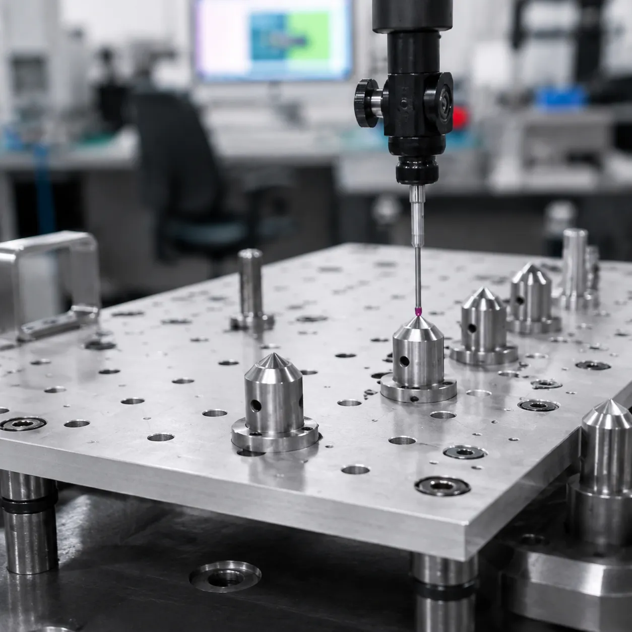
Position tolerance defines the exact boundary for hole centers relative to the specified datum reference frame.
- Cylindrical Zone: Defines a round tolerance zone around the true position that mirrors actual round dowel pins, maximizing usable manufacturing tolerance compared to square coordinate zones.
- Pin Alignment: Prevents pin binding and guarantees exact centerline alignment every time a plate is mounted or swapped in production.
Flatness of Mounting and Seating Surfaces
Flatness forms the foundation of locator plate repeatability by controlling surface variation between two parallel planes without referencing external datums.
- Stable Seating: Prevents plate warping, twisting, or rocking when mounting bolts are torqued down.
- Assembly Integrity: Ensures uniform contact pressure when mounting plates onto components like custom anodized mounts and brackets for OEM packaging.
Perpendicularity Between Critical Features and Datum Surfaces
Perpendicularity controls 90-degree angular relationships between functional faces or hole axes and the primary base datum.
- Vertical Precision: Guarantees locating pins stand perfectly upright, preventing product jamming during vertical loading or indexing cycles.
- Square Edge Locating: Ensures side alignment rails maintain true squareness for accurate edge-referencing across production runs.
Profile Controls for Complex Machined Features
Profile of a surface bounds complex pocket geometries and custom outer contours within a uniform 3D tolerance envelope.
- All-in-One Control: Simultaneously manages feature size, orientation, and location against functional datums in a single feature control frame.
- Custom Pocketing: Delivers precise fit clearances for specialized packaging shapes without over-tolerancing non-critical edges.
How Position Tolerance Controls Locating Pin and Hole Patterns
Position tolerance is the core GD&T tool we use to guarantee that hole patterns and locating pins align perfectly across every production batch.
Understanding the Position Tolerance Zone
Instead of relying on rigid square boundary boxes, position tolerance establishes a cylindrical tolerance zone centered around the feature's true position.
- 360-Degree Uniformity: The cylindrical zone allows equal deviation in all directions from the theoretical exact location.
- 57% More Usable Area: Compared to a traditional square tolerance zone of the same width, a circular zone provides 57% more functional tolerance area without sacrificing assembly fit.
- Feature Axis Control: It controls both the location and orientation of the hole’s center axis, keeping locating pins straight and true.
Controlling Hole Location Relative to Functional Datums
A hole pattern cannot exist in isolation; it must relate directly to how the locator plate mounts to the machine chassis.
- Basic Dimensions: We specify exact theoretical distances from designated datum planes using basic dimensions.
- Datum Framework: The feature control frame ties the cylindrical tolerance zone back to the primary, secondary, and tertiary datums.
- Fixed Orientation: This setup prevents pattern tilt or drift relative to the seating surfaces, ensuring every locating pin mates cleanly with the matching component.
Why Coordinate ± Tolerances and Position Tolerance Are Not Equivalent
Traditional ± coordinate tolerances often fail in high-precision packaging machine assemblies. Understanding how to manage tolerance stack-up reveals why true position control outperforms square coordinate limits.
| Feature Aspect | Coordinate ± Tolerances | GD&T Position Tolerance |
|---|---|---|
| Zone Shape | Square or rectangular | Cylindrical (circular) |
| Corner Variation | Permits extreme diagonal variance | Uniform boundary in all radial directions |
| Datum Reference | Vague or implicit origin points | Explicit functional datum reference frame |
| Bonus Tolerance | None available | Allowed when applying Maximum Material Condition (MMC) |
How Hole-Pattern Error Affects Replacement Plate Alignment
When a locator plate wears out on a high-speed production line, maintenance teams need a quick drop-in replacement. Hole-pattern errors destroy this interchangeability.
- Pin Binding: Slight spacing deviations between dowel holes force locating pins to bind during installation.
- Assembly Shift: Pattern rotation causes entire fixture plates to mount out of square, leading to downstream alignment errors.
- Downtime Risks: Poor locator plate repeatability forces operators to custom-ream holes or modify mounting setups on the factory floor, spiking costly operational downtime.
MMC, RFS, and Functional Fit in Locator Plate Design
What Maximum Material Condition (MMC) Means
In locator plate GD&T, Maximum Material Condition (MMC)—represented by the symbol in a feature control frame—defines the condition where a feature contains the maximum amount of material within its specified dimensional limits.Internal Features (Holes): MMC occurs at the smallest permitted hole size.
- External Features (Pins/Blocks): MMC occurs at the largest permitted feature size.
Applying MMC to mounting and bolt patterns ensures that components will always assemble, even under worst-case manufacturing conditions.
- How Bonus Tolerance Works With Features of Size
When you apply MMC to a position tolerance, any growth in hole size away from MMC yields additional positional tolerance, known as bonus tolerance. As a clearance hole is machined larger toward its Least Material Condition (LMC), mating clearance increases, allowing the center location to shift without compromising physical assembly.
| Hole Diameter State | Hole Size | Base Position Tolerance | Bonus Tolerance | Total Allowed Position Tolerance |
|---|---|---|---|---|
| MMC (Smallest) | 10.00 mm | 0.05 mm | 0.00 mm | 0.05 mm |
| Nominal | 10.05 mm | 0.05 mm | 0.05 mm | 0.10 mm |
| LMC (Largest) | 10.10 mm | 0.05 mm | 0.10 mm | 0.15 mm |
Bonus tolerance lowers scrap rates and machining costs without risking assembly fit. For high-speed production packaging equipment, pairing properly toleranced metal plates with high-performance CF PEEK conveyor wear parts maintains smooth operation across millions of cycles.
- When RFS May Be Appropriate for Critical Locating Features
Regardless of Feature Size (RFS) is the default rule in modern ASME standards. Under RFS, the stated geometric tolerance remains fixed regardless of the feature's actual finished size; no bonus tolerance is granted.
We specify RFS for critical locating features where axis drift or looseness cannot be tolerated:
Precision Dowel Pin Holes: Prevents alignment shift between mating plates.
Press-Fit Pin Joints: Holds strict centerlines for fixed shafts and locators.
High-Precision Tooling Centers: Maintains absolute locator plate repeatability during aggressive indexing.
Why Material Condition Modifiers Should Follow Functional Requirements
Selecting the right material condition modifier keeps parts functional without over-engineering the manufacturing process.Clearance & Fastener Holes: Use MMC to optimize tolerance budgets while guaranteeing bolt pass-through.
- Precision Locating Features: Use RFS to lock down true position and maintain strict datum alignment.
- Datum Features of Size: Apply MMC modifiers to secondary or tertiary datums only when pattern shift is functionally acceptable relative to the primary datum reference frame.
How GD&T Affects Replacement Locator Plate Interchangeability
When swapping out a worn plate on an active production line, direct drop-in replacement is essential. Proper locator plate GD&T ensures that replacement components fit immediately without manual shimming, re-reaming, or line adjustments.
Maintaining the Same Datum Structure Across Replacement Parts
Ensuring true swapability requires locking in a consistent datum reference frame across every production batch. We reference critical features back to established primary, secondary, and tertiary datums so that every manufactured part shares identical baseline coordinates.
- Fixed Reference Planes: Primary contact surfaces remain identical across old and new revisions.
- Orientation Consistency: Eliminates part-to-part rotation variations during installation.
- Seamless Field Swaps: Technicians can replace worn plates instantly during scheduled maintenance.
Controlling Dowel Hole and Mounting Feature Relationships
A primary cause of replacement failure is the geometric offset between alignment pins and securing bolts. Applying position tolerance controls the precise relationship between dowel holes and clearance holes.
| Feature Type | Control Method | Functional Purpose |
|---|---|---|
| Dowel Pin Holes | Tight True Position | Establishes precise datum alignment and location. |
| Mounting Bolt Holes | Broader Position Zone | Provides fastener clearance without inducing mechanical stress. |
Preventing Tolerance Stack-Up During Machine Assembly
Standard coordinate plus/minus tolerances accumulate quickly across mating components. Controlling the location of functional features relative to fixed datums prevents tolerance stack-up during packaging machine assembly. This tight geometric control preserves exact locator plate repeatability across multi-part subassemblies, preventing misalignment issues downstream.
Why Individual Feature Accuracy Alone Does Not Ensure Assembly Repeatability
Machining a hole to an exact diameter does not guarantee it will align with a mating pin. If the geometric relationship between hole centers and locating surfaces shifts, the plate will bind during installation.
- Feature Size vs. Location: Hole diameter controls fit, but true position controls location.
- Geometric Control: GD&T ties isolated dimensions into a unified functional framework.
- Guaranteed Interchangeability: Parts meet overall mechanical function, not just isolated dimensional checks.
- CNC Machining Challenges for GD&T-Controlled Locator Plates
Establishing Machining Datums From the Drawing
Matching physical workholding to the print's specified datum reference frame is our first priority on the shop floor. Setting up raw stock without aligning strictly to primary and secondary datums causes immediate position errors across downstream features. When tackling complex geometry or multi-sided setups, leveraging high-precision strategies such as 5-axis custom CNC machining allows us to establish true position and maintain exact feature locations in a single clamping setup.
Controlling Flatness Before Critical Hole Finishing
Base surface flatness directly dictates overall locator plate repeatability. Drilling or reaming precision dowel holes into a bowed plate guarantees location drift once clamping forces are released.
- Material Normalization: Stress-relieve raw plate stock prior to finish facing to prevent spring-back.
- Light Skim Cuts: Use high-speed finish passes with sharp tooling to eliminate localized heat buildup and surface tension.
- In-Process Verification: Inspect base plane flatness before executing final hole-pattern operations.
Reaming and Finishing Precision Locating Holes
Meeting strict position tolerance specs on dowel holes requires tight process control during final sizing. Standard circular interpolation milling often leaves microscopic lobing that compromises locating pin tolerance fits.
| Finishing Step | Target Control | Key Manufacturing Objective |
|---|---|---|
| Precision Boring / Reaming | Hole Diameter & Roundness | Ensures exact interference or slip-fit tolerances |
| In-Situ True Position Checks | Centerline Location | Verifies hole spacing relative to datums before breaking setup |
| Deburring & Chamfering | Edge Integrity | Prevents micro-burrs from throwing off assembly alignment |
Managing Distortion in Large or Thin Locator Plates
Large, thin-section plates tend to warp under aggressive tool engagement or heavy clamping pressure.
- Equalized Stock Removal: Alternate light face cuts between top and bottom surfaces to balance internal material stresses.
- Low-Stress Fixturing: Utilize vacuum chucks or specialized toe-clamps to secure the plate without inducing artificial bending.
- Thermal Management: Maintain consistent coolant flow to eliminate thermal expansion during tight-tolerance hole finishing.
- How to Inspect a GD&T-Controlled Locator Plate
CMM Inspection of Position and Datum Relationships
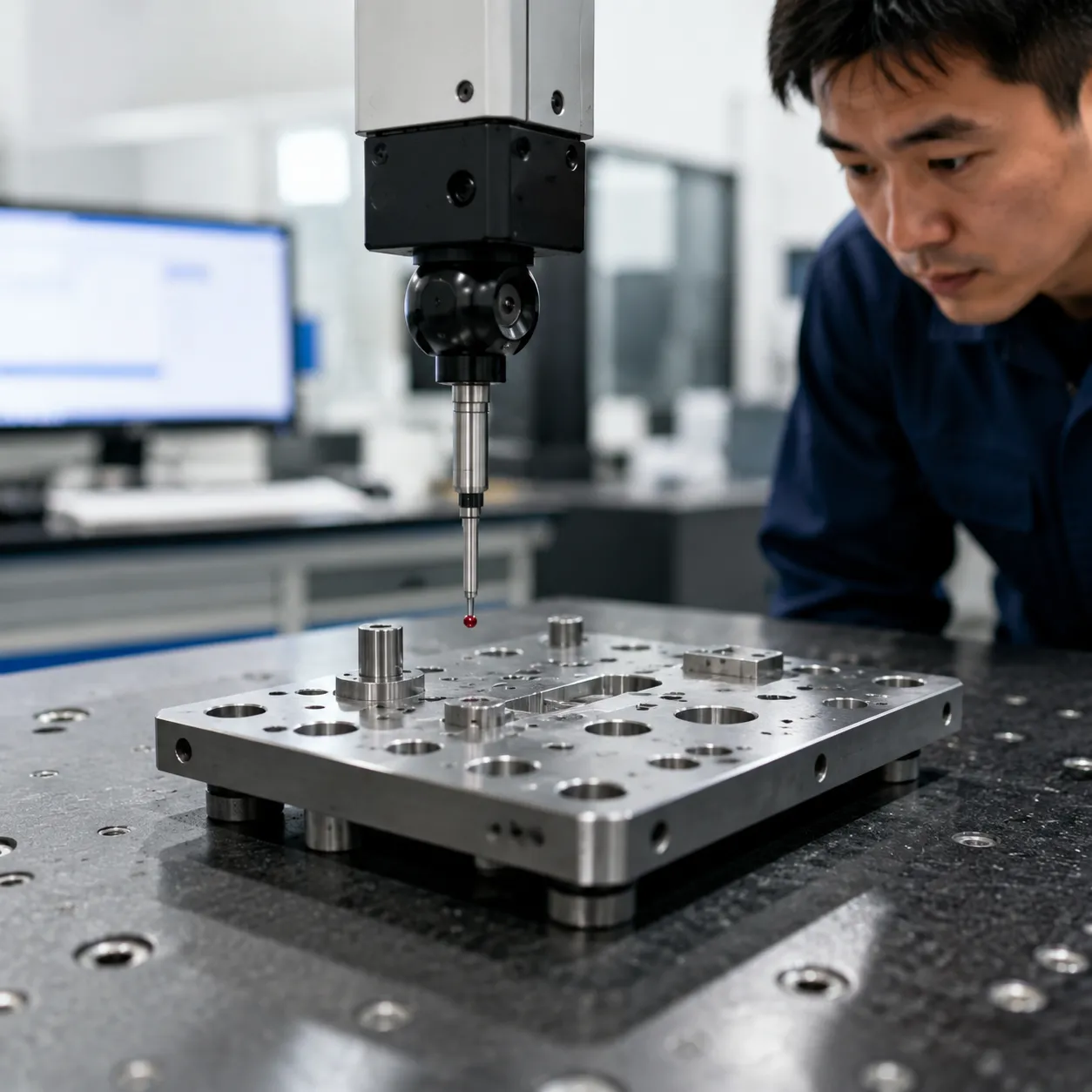
Coordinate Measuring Machines (CMMs) are essential for evaluating locator plate GD&T callouts accurately. A CMM calculates position tolerance by evaluating hole and pin centerlines directly against the active datum reference frame.
- Probe physical datums first: Establish primary, secondary, and tertiary surfaces exactly as specified on the print.
- Construct the coordinate alignment: Mirror the drawing's mathematical structure inside the software before taking feature measurements.
- Verify true position: Measure dowel hole locations relative to the constructed frame rather than physical part edges.
We rely on comprehensive quality inspection services to verify tight position tolerances and ensure total assembly repeatability before parts hit the packaging line.
Checking Flatness and Perpendicularity
Surface controls guarantee that the locator plate sits flush without introducing angular tilt into the machine frame.
- Flatness Verification: Sweep mounting surfaces using a CMM grid or dial indicator on a granite surface plate to detect bowing or twist.
- Perpendicularity Verification: Measure side locating edges against the primary datum plane to prevent binding during part insertion.
| Inspection Tool | GD&T Control Verified | Primary Application |
|---|---|---|
| CMM Touch Probe | Position tolerance, datum alignment | Critical dowel holes & pin patterns |
| Dial Indicator & Surface Plate | Flatness, parallelism | Base mounting faces & seating pads |
| Functional Pin Gages | MMC true position, virtual condition | Fast pass/fail assembly fit checks |
Functional Gaging for Locating Features When Appropriate
When drawings specify Maximum Material Condition (MMC) modifiers on locating holes, functional hard gages provide a rapid, practical check.
- Simulate Mating Parts: Hard gages use fixed pins sized to the feature's virtual condition boundary.
- Instant Fit Verification: If the gage inserts smoothly, the plate will fit correctly in the packaging machine, accounting for any allowable bonus tolerance.
- Streamline Inspection: Functional gages eliminate lengthy CMM routine setups for high-volume replacement part runs.
Why Inspection Setup Must Follow the Drawing Datum Structure
Inspecting a locator plate out of datum sequence leads to false rejections or, worse, passing parts that fail during machine assembly.
- Restrain the Part Correctly: Secure the plate against the primary datum surface first, just as it bolts into the final assembly.
- Eliminate Setup Ambiguity: Never reference physical plate edges unless those edges are designated as functional datums.
- Ensure Repeatable Results: Matching the inspection setup to the datum reference frame guarantees that quality reports reflect real-world alignment accuracy.
Common GD&T Mistakes on Locator Plate Drawings
Poorly applied engineering drawings hurt manufacturing efficiency and compromise locator plate repeatability. We routinely spot drawing errors that increase production costs without improving packaging machine alignment.
Over-Tolerancing Non-Critical Features
Applying tight geometric controls to non-mating surfaces inflates CNC machining time without performance gains.
- Cost Impact: Ultra-tight limits on external non-mating edges or simple clearance holes increase scrap rates.
- Best Practice: Reserve tight position tolerance strictly for locating dowel holes and primary seating faces.
| Drawing Mistake | Functional Consequence | Corrective Action |
|---|---|---|
| Excessive flatness callouts on clearance surfaces | High scrap rates, longer setup times | Apply standard stock tolerances to non-mating faces |
| Overly strict true position on oversized bolt holes | Assembly rejection over minor hole shifts | Use generous position tolerances with MMC modifiers |
Using Datums That Do Not Reflect Functional Assembly
Your datum reference frame must mirror physical assembly constraints. Choosing arbitrary raw edges instead of functional mating faces ruins datum alignment. Just as we see in precision tooling like sealing jaws heat plates for tray sealers, a locator plate requires datums anchored directly to actual mounting contact points.
- Datum Shift: Incorrect primary datums introduce angular tilt during installation.
- Proper Hierarchy: Set the primary datum on the main mounting surface, with secondary and tertiary datums derived from key locating features.
Applying Tight Position Tolerances Without Considering Fit
Specifying rigid positional limits without evaluating pin-to-hole clearance leads to unnecessary part rejections.
- Missing MMC Modifiers: Omitting maximum material condition (MMC) from the feature control frame eliminates bonus tolerance as hole sizes grow.
- Fit Mismatch: Over-specifying locating pin tolerance without accounting for pin clearance makes assembly unnecessarily difficult.
Specifying GD&T That Cannot Be Reliably Inspected
Geometric callouts are ineffective if quality control cannot measure them repeatably.
- Unreachable Features: Defining datums on micro-features or hidden edges that probes cannot easily touch.
- Flexible Surfaces: Expecting repeatable CMM inspection results on thin, unsupported plate sections that warp when unclamped.
- Inspection Protocol: Design datum features with enough surface area for stable fixture clamping and CMM touch-probing.
What to Include When Ordering a Custom Locator Plate
Provide the Complete 2D Drawing and 3D CAD Model
Both 3D models and fully detailed 2D prints are essential when ordering custom machine components. The 3D CAD file provides exact solid geometry for CNC programming, while the 2D engineering drawing establishes the binding quality standards. The 2D print must detail all geometric dimensioning and tolerancing (GD&T) requirements, allowable basic dimensions, and feature control frames to ensure predictable locator plate repeatability.
Identify Critical Datum and Locating Features
We build precision parts directly from your specified datum reference frame. Clear callouts prevent manufacturing ambiguity and align our CNC machining setups with your physical machine assembly.
- Primary Datum: Defines the main seating surface to control planar orientation.
- Secondary & Tertiary Datums: Control rotation and translation across dowel holes or key edges.
- Locating Features: Highlight all critical pin locations, true position tolerances, and press-fit hole callouts.
Define Material, Surface Finish, and Quantity Requirements
Material selection and post-processing dictate part longevity, thermal stability, and assembly alignment. Specifying our advanced surface finishing capabilities ensures mounting faces remain flat, burr-free, and resistant to wear under high packaging cycle speeds.
| Ordering Requirement | Technical Specification | Functional Purpose |
|---|---|---|
| CAD & Print Package | STEP/IGES model + 2D PDF drawing | Defines 3D geometry and binding GD&T specifications |
| Datum Structure | Primary, secondary, tertiary callouts | Establishes 3-2-1 locating alignment for machining |
| Material & Finish | Tool steel, stainless, or anodized aluminum | Ensures structural rigidity and corrosion resistance |
| Surface Finish | Specified Ra values for seating faces | Prevents tilt and guarantees flat surface contact |
| Production Volume | Prototype, spare parts, or batch quantity | Determines tooling setups and unit pricing |
Specify Inspection and Reporting Requirements
To guarantee total interchangeability for replacement plates, state your quality verification criteria before manufacturing begins.
- CMM Inspection Reports: Request coordinate measuring machine verification for critical position tolerances and datum relationships.
- First Article Inspection (FAI): Require full FAI documentation for initial prototype or production runs.
- Functional Gaging: Specify if fixed pin or hard gaging is acceptable for maximum material condition (MMC) feature evaluation.