How Surface Finish Affects Sealing and Sliding Components
Precision machinery relies on exact surface micro-geometries to ensure functional reliability. In packaging machinery and automated systems, the surface finish directly dictates seal integrity, friction control, and component longevity.
Why Surface Finish Matters Beyond Appearance
Surface texture is a critical functional specification, not a cosmetic preference. Machined surfaces interact at the microscopic level, where subtle surface profile variations govern physical contact mechanics.
- Seal Performance: Prevents micro-leakage pathways across mating surfaces under hydraulic or pneumatic pressure.
- Friction and Wear: Controls the coefficient of friction, operating temperatures, and wear rates on sliding components.
- Hygiene and Cleanability: Eliminates microscopic valleys that trap product residue, bacterial growth, or corrosive agents in washdown environments.
- Component Lifespan: Minimizes premature abrasive wear on wear strips, guide rails, and mating soft seals.
Understanding Surface Roughness, Waviness, and Lay
Total surface texture consists of three distinct geometric components created during the manufacturing process.
| Parameter | Definition | Cause | Impact on Components |
|---|---|---|---|
| Roughness | Small-scale, closely spaced surface irregularities | Cutting tool action, abrasive grains, or chip formation | Directly affects friction, local contact pressure, and seal wear |
| Waviness | Broader, periodic surface variations | Workpiece deflection, thermal distortion, or machine chatter | Causes uneven load distribution and continuous seal bypass paths |
| Lay | The predominant direction of the surface pattern | Tool motion path (e.g., parallel, perpendicular, radial, multidirectional) | Determines fluid leakage direction and sliding friction behavior |
What Ra Measures—and What Ra Does Not Tell You
Roughness Average ($Ra$) is the standard parameter specified on engineering drawings, representing the arithmetical mean of surface profile heights over a evaluation length. While $Ra$ offers a baseline quality metric, it provides an incomplete picture of functional performance.
What Ra Provides:
A universally recognized single-value benchmark for general quality control.
A simple, cost-effective measurement via standard contact profilometers.
An accurate reflection of overall surface height variations.
What Ra Fails to Reveal:
Peak vs. Valley Profile: $Ra$ cannot distinguish between a surface with sharp peaks (which abrade seals) and a surface with deep valleys (which hold lubricant).
Surface Geometry Shape: Two surfaces with identical $Ra$ values can exhibit vastly different profile shapes and contact areas.
Directionality: $Ra$ provides no information regarding surface lay, which dictates whether fluids can flow along tool marks past a sealing interface.
How Surface Finish Affects Packaging Sealing Components
Contact Between Machined Sealing Faces
When two sealing faces meet, contact only occurs at microscopic high points (asperities). In packaging machinery, this real contact area dictates whether heat transfers uniformly across packaging film or fluid remains contained within liquid filling lines. We engineer our custom CNC packaging sealing jaws and guide components to achieve optimal contact area, eliminating leak paths before components go into production.
How Tool Marks and Surface Irregularities Affect Contact Conditions
CNC machining leaves behind micro-grooves based on cutter geometry, feed rates, and toolpaths. How these tool marks align relative to the seal direction determines sealing success.
- Perpendicular Tool Marks: Create continuous micro-channels across the seal face, leading to fluid bypass or vacuum loss under pressure.
- Parallel Tool Marks: Block transverse fluid movement, helping maintain seal integrity along the interface.
- Sharp Peak Heights: Concentrated contact points can tear delicate flexible barrier films or create local hot spots during heat sealing operations.
Flatness vs. Surface Roughness: Why They Are Not the Same
A surface can have a mirror-like Ra value and still fail to seal if it lacks overall geometric flatness. Distinguishing micro-scale roughness from macro-scale flatness prevents costly design mistakes. For a breakdown of these interactions in heat-sealing applications, review our tray sealer sealing jaw surface finish guide.
| Property | Scale | What It Measures | Impact on Sealing |
|---|---|---|---|
| Surface Roughness | Microscopic (microns) | Fine texture, peak-to-valley heights (Ra, Rz) | Controls local contact pressure and micro-channel formation |
| Flatness | Macroscopic (millimeters) | Planar deviation across the full face length | Prevents gross gap formation and uneven clamping force |
Why Seal Performance Depends on More Than Surface Finish
Achieving an ultra-smooth sealing surface finish is only one part of the engineering equation. Reliable sealing performance relies on a balance of several mechanical variables.
- Clamping Force Distribution: Insufficient or uneven bolt pre-load leaves microscopic gaps open regardless of low Ra values.
- Thermal Expansion & Distortion: Heat sealing jaws warp at operating temperatures if thermal expansion and structural mass are not properly calculated.
- Material Compliance: Softer seal layers (elastomers or PE films) conform to higher surface roughness, while rigid metal-to-metal sealing faces require tight surface roughness limits.
How Surface Finish Affects Sliding and Guide Components
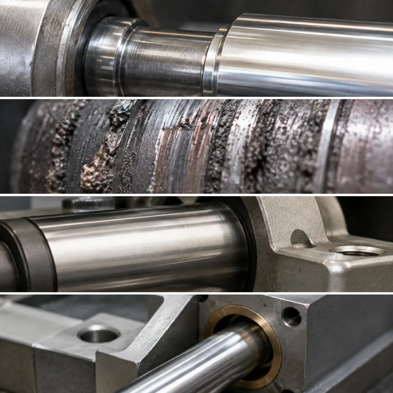
Friction at Sliding Contact Surfaces
In high-speed packaging machinery, sliding surface finish directly dictates the coefficient of friction between mating components. When surface roughness is unmanaged, microscopic contact points generate excessive frictional drag, increasing motor loads and heat build-up. We optimize the surface texture of packaging machine guide components to maintain smooth motion and consistent throughput.
Surface Peaks, Wear, and Running-In Behavior
Every machined surface features micro-peaks (asperities) and valleys. During the initial running-in phase, these peaks shear off under load, shifting the friction dynamics:
- Initial Peak Shearing: High contact pressure flattens asperities rapidly.
- Debris Generation: Sheared particles act as third-body abrasives if not flushed out.
- Steady-State Stabilization: Wear rates level off once the actual contact area expands.
When a Smoother Surface Can Reduce Abrasive Interaction
Lowering the Ra value reduces mechanical interlocking between sliding surfaces, protecting softer components like plastic wear strips from premature gouging. For aggressive environments, combining fine finishes with specialized hardware—such as PET food wear tracks and DLC-coated components—drastically lowers abrasive wear while extending service intervals.
Why the Smoothest Possible Surface Is Not Always the Best Specification
Achieving the absolute lowest Ra value is often counterproductive for sliding applications due to specific physical limitations:
| Surface Condition | Physical Impact | Functional Result |
|---|---|---|
| Mirror Finish (< 0.1 µm Ra) | High static friction (stiction) & oil film wipe-off | Lubricant starvation, wringing, and sudden seizure |
| Controlled Finish (0.4–0.8 µm Ra) | Retains cross-hatch valleys for lubrication | Continuous hydrodynamic film and predictable wear |
| Over-Machined Spec | Unnecessary polishing passes | Exponentially higher CNC machining costs without performance gains |
Surface Finish Considerations for Different Packaging Components
Different packaging machine guide components and sealing elements face distinct mechanical and environmental demands. Tailoring the surface finish for packaging machine components depends directly on whether the part manages heat transfer, continuous friction, or strict hygienic washdowns.
| Component Type | Primary Function | Recommended Ra Range | Key Surface Finish Target |
|---|---|---|---|
| Heat Sealing Jaws | Thermal sealing & foil/film compression | 0.8–1.6 µm (32–63 µin) | Uniform thermal contact without film adhesion |
| Metal Guide Rails | Linear guidance & sliding support | 0.4–0.8 µm (16–32 µin) | Reduced sliding friction and galling prevention |
| Plastic Guides (UHMW / POM) | Low-drag wear strips & star wheels | 0.8–3.2 µm (32–125 µin) | Smooth surface free of polymer burrs or tearing |
| Washdown Stainless Components | Product contact & sanitary handling | < 0.8 µm (< 32 µin) | Non-porous, corrosion-resistant, easy-to-clean face |
Heat Sealing Jaws and Sealing Bars
Heat sealing relies on consistent contact pressure and quick film release. If the sealing surface finish is too rough, molten packaging film melts into microscopic tool marks, causing buildup, burnt film, and seal leaks. We produce precision sealing jaws and heat plates designed to balance heat transfer with clean release characteristics.
Metal Guide Rails and Sliding Components
High-speed container handling creates continuous friction and wear along metal guide rails. An improper sliding surface finish leads to chatter, container scuffing, and early component failure. For high-load and high-wear environments, we manufacture custom titanium guide components and hardened steel tracks machined with fine lay patterns to maintain smooth motion.
UHMW-PE and POM Guide Components
Machining polymers like UHMW-PE and POM requires specific tool geometries to avoid material melting or surface fuzzing. Rough wear strips increase drag on conveyor lines and trap abrasive dust. Controlling the CNC surface finish on plastic guides ensures low friction, quieter line operation, and longer service life.
Stainless Steel Product-Contact and Washdown Components
In food and pharmaceutical packaging, surface roughness directly impacts cleanability. High Ra values create micro-crevices where bacteria and product residues collect. We finish stainless steel washdown components to strict Ra targets, combining precise machining with electropolishing to ensure smooth, corrosion-resistant surfaces that withstand aggressive chemical washdowns.
Ra, Rz, Lay, and Other Surface Characteristics
Understanding Ra as an Average Roughness Parameter
Ra (Roughness Average) measures the mean arithmetic deviation of a surface profile along a evaluation length. While it gives a quick, universally accepted snapshot of overall surface roughness, it flattens out critical structural details. Ra treats high peaks and low valleys equally, which means it serves as a helpful baseline for general surface finish for packaging machine components, but fails to reveal the actual shape of the surface profile.
Why Two Surfaces With Similar Ra Can Behave Differently
Two machined parts can share the exact same Ra value yet perform drastically differently in real-world packaging environments. A surface dominated by sharp, jagged peaks will slice through soft elastomers and accelerate component breakdown. Conversely, a surface with plateaued peaks and deep valleys retains oil efficiently and glides smoothly under load.
| Profile Profile Feature | Impact on Sealing Surfaces | Impact on Sliding Surfaces |
|---|---|---|
| Sharp Peaks | Pierces soft seal materials, causing premature leakage | Dramatically increases initial friction and wear, risking galling |
| Deep Valleys | Creates potential micro-leakage pathways across mating faces | Retains liquid lubricants, supporting sustained hydrodynamic motion |
| Rounded / Plateau Peaks | Distributes clamping force evenly for a tight seal | Minimizes contact resistance and extends mating part life |
How Surface Lay Can Matter in Sliding Applications
Surface lay defines the predominant direction of the surface pattern produced by CNC toolpaths. In dynamic systems, tool mark orientation dictates how mating components interact:
- Perpendicular Lay: Machining lines run crosswise to the direction of motion, increasing drag and continuously wiping away protective lubricant films.
- Parallel Lay: Tool marks align with the direction of movement, offering lower drag and smooth linear tracking for sliding surface finish applications.
- Multi-directional Lay: Non-directional finishes maintain small oil pockets across all movement vectors, making them ideal for complex, high-load dynamic contact zones.
Pairing proper surface lay with advanced material selection—such as specifying CF-PEEK for conveyor wear parts—ensures minimal mechanical drag and prevents premature surface breakdown.
When Additional Surface Parameters May Be Required
Relying solely on Ra for critical packaging machine guide components or high-pressure sealing surface finish specs leaves too much to chance. For high-stakes functional areas, supplementary parameters ensure predictable operation:
- Rz (Maximum Height of Profile): Measures the vertical distance between the highest peak and deepest valley within a sampling length. It flags extreme profile spikes that Ra averages out, protecting sensitive seals.
- Rpk (Reduced Peak Height): Quantifies the top peaks that will wear down during initial run-in, helping predict early wear behavior.
- Rvk (Reduced Valley Depth): Measures the fluid retention capacity of deep valleys, ensuring sufficient lubrication under continuous operation.
- How CNC Machining Creates Surface Finish
Every micro-groove left on a CNC machined part directly reflects the physical interaction between the cutting edge, the machine tool, and the raw material. Controlling CNC machining surface roughness requires balancing several interconnected cutting parameters during production.
Tool Geometry and Cutting Edge Condition
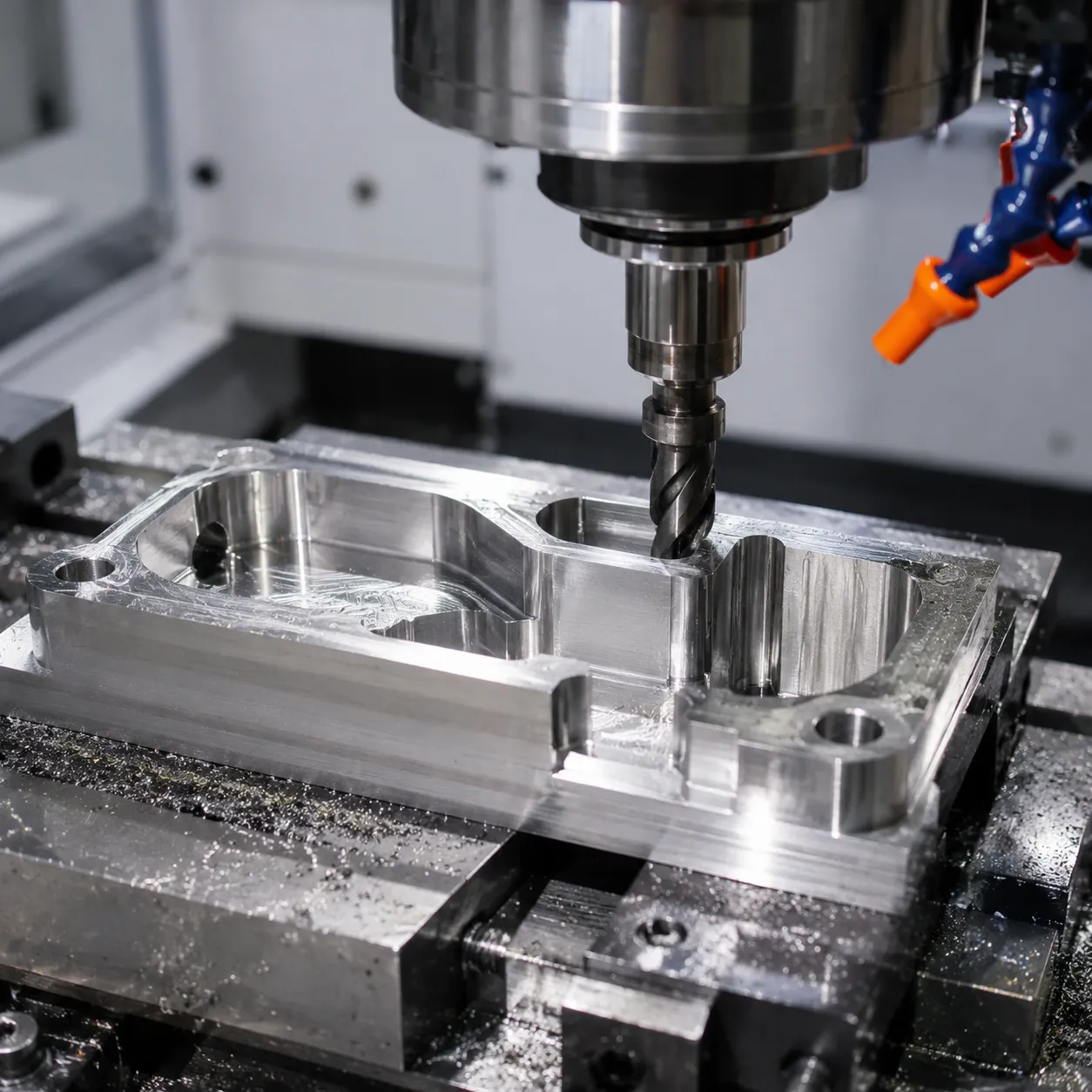
The physical geometry and sharp edge of the cutting insert set the baseline for sealing surface finish and sliding quality.
- Insert Corner Radius: A larger nose radius flattens the peak-to-valley profile between passes, directly reducing the theoretical Ra value.
- Edge Preparation: Razor-sharp cutting edges shear material cleanly. Dulle, worn, or chipped inserts tear the metal, creating localized burrs and elevated roughness.
- Rake and Clearance Angles: Proper rake angles facilitate smooth chip evacuation, preventing chip recutting that mars finished surfaces.
Feed, Speed, and Toolpath Effects
Tool motion across the workpiece dictates the final feed marks and surface texture.
- Feed Rate: Lowering the feed rate per tooth decreases scallop heights. However, excessively low feed rates cause tool rubbing rather than cutting, which degrades surface quality.
- Cutting Speed (RPM): Higher cutting speeds minimize built-up edge (BUE) formation on the cutter, yielding a cleaner finish on ductile materials.
- Toolpath Strategy: Advanced toolpath programming maintains consistent tool engagement. Utilizing specialized CAM profile machining techniques prevents cutter dwell marks and ensures uniform sliding surface finish across complex contours.
Machine Rigidity, Vibration, and Chatter
Dynamic instability during cutting damages both sealing lands and wear-strip contact tracks.
| Cause | Effect on Surface Finish | Mitigation Strategy |
|---|---|---|
| Tool Deflection | Creates tapered cuts and inconsistent Ra values along the pass. | Use shorter tool overhangs and stiffer carbide shanks. |
| Harmonic Chatter | Leaves cyclic wave patterns and severe micro-peaks across the part. | Adjust spindle RPM, alter feed rates, or use variable-helix end mills. |
| Spindle Runout | Causes uneven chip loading, leaving periodic tool marks on the wall. | Maintain precision spindle bearings and balanced tool holders. |
Material Properties and Their Effect on Machined Surfaces
Each material behaves differently under the mechanical stress of CNC cutting, impacting the final surface finish for packaging machine components:
- 304/316 Stainless Steel: Prone to work-hardening and gummy chips. Requires high rigidity, sharp tooling, and consistent coolant flow to prevent surface tearing on food-contact components.
- Aluminum Alloys (6061-T6 / 7075-T6): Machine exceptionally well to ultra-low Ra values, provided high cutting speeds and adequate lubrication prevent edge welding.
- Engineering Plastics (UHMW-PE & POM): Low melting points and high elasticity require razor-sharp, polished flutes to shear the plastic cleanly without melting or creating fibrous surface fuzz.
- Post-Machining Processes for Surface Improvement
Standard CNC milling and turning leave microscopic tool marks on machined parts. To achieve specific sealing or sliding performance, secondary finishing processes are often required to refine surface topology beyond raw machining capabilities.
Mechanical Polishing and Grinding
Mechanical grinding removes tool marks, chatter, and waviness to create flat, stable reference surfaces. Polishing further reduces peak heights, lowering surface roughness for dynamic seals and sliding contact faces.
- Precision Grinding: Eliminates high spots that cause localized seal compression and corrects tight geometric tolerances.
- Mechanical Polishing: Brings Ra values down to 0.2–0.4 µm, preventing premature wear on soft elastomers during repeated motion.
Electropolishing for Appropriate Stainless Steel Components
Electropolishing electrochemically levels the microscopic profile of stainless steel parts. Instead of mechanically smearing metal, it selectively dissolves surface peaks, rounding micro-edges and leaving a passive oxide layer.
- Sealing Protection: Eliminates microscopic burrs that can tear or nick soft sealing rings during installation or operation.
- Sanitary and Fluid Control: Improves cleanability in wet washdown environments. For instance, electropolishing 316L valve manifolds ensures reliable seal seating and prevents fluid trapping in micro-crevices.
Anodizing and Surface Treatment of Aluminum Components
Anodizing builds a hard aluminum oxide layer that enhances corrosion and wear resistance on sliding components. However, anodizing replicates the underlying surface texture rather than smoothing it out.
- Hardcoat Anodizing (Type III): Significantly increases surface hardness for low-friction wear plates and guide rails.
- Pre-Finish Surface Preparation: Machining marks must be polished out prior to surface treatment when manufacturing custom 6061-T6 aluminum CNC parts for packaging machines, preventing underlying tool lines from compromising the hardcoat finish.
Why the Finishing Process Should Follow Functional Requirements
Selecting a finishing technique based purely on visual appearance increases processing costs without guaranteeing better performance. Each finishing method alters surface structure differently, making it critical to align the process with the mechanical demands of the component.
| Finishing Process | Typical Ra Range (µm) | Key Functional Impact | Target Components |
|---|---|---|---|
| Precision Grinding | 0.4 – 0.8 | Improves flatness and eliminates chatter | Static sealing faces, linear guides |
| Electropolishing | 0.2 – 0.4 | Removes micro-burrs and improves corrosion resistance | Stainless fluid manifolds, valve seats |
| Hard Anodizing | Matches substrate | Enhances surface hardness and wear resistance | Aluminum sliding tracks, guide blocks |
| Precision Lapping | < 0.2 | Creates ultra-flat, mirror-like contact faces | High-pressure gas seals, vacuum plates |
Matching post-machining operations directly to the sealing or sliding function ensures predictable friction, tight sealing, and longer service life for custom machine components.
How to Specify Surface Finish on a Packaging Part Drawing
Identify Functional Surfaces Instead of Applying One Ra Everywhere
Slapping a single tight Ra value across an entire title block drives up CNC machining costs without adding performance value. We separate critical wear and contact faces from non-functional outer surfaces directly on the engineering print.
- Sealing Faces & Sliding Tracks: Require tight, controlled surface finish values.
- Structural Frames & Outer Housings: Standard mill finishes are completely sufficient.
- Mounting Interfaces: Moderate finishes ensure solid planar contact without extra polishing operations.
Specify Roughness Only Where It Affects Function
Over-specifying surface finish creates unnecessary machine runtime, tool wear, and secondary grinding steps. We recommend calling out explicit surface roughness targets strictly where friction, dynamic sealing, or sanitation demands it.
| Surface Role | Typical Ra Target | Primary Function |
|---|---|---|
| Dynamic Seals | 0.2 – 0.4 µm | Prevents fluid/air leak paths under pressure |
| Sliding Guides | 0.4 – 0.8 µm | Minimizes friction and extends component wear life |
| Washdown Contact | 0.8 µm | Eliminates micro-crevices for sanitation |
| Non-Contact Clearance | 3.2 µm | Standard efficient CNC machining |
Consider Flatness, Parallelism, and Geometry Separately From Roughness
A surface can feature a mirror-smooth Ra 0.2 µm finish and still fail if the component is bowed or warped. Surface roughness measures micro-profile peaks, whereas flatness and parallelism control macro-geometry. When designing precise changeover assemblies, understanding how tolerance stack-up affects packaging change part fit ensures that geometric controls (GD&T) work in tandem with surface finish specs.
- Flatness Callouts: Ensure uniform surface contact across wide heat-sealing jaws.
- Parallelism Controls: Keep sliding guide channels aligned to eliminate binding.
- Roughness Callouts: Control micro-friction and seal lip wear.
Define Post-Finishing Requirements When Needed
Secondary operations alter final surface topography. On part drawings, always clarify whether specified surface finish requirements apply before or after post-machining treatments.
- Coatings & Plating: Surface treatments can alter profile dimensions and slightly increase surface roughness.
- Electropolishing: Smooths microscopic peaks, improving corrosion resistance and lowering effective Ra.
- Material-Specific Treatments: When specifying hard anodized aluminum vs 316L stainless packaging parts, indicate whether mechanical grinding or bead blasting must occur prior to anodizing or passivating.
How Surface Finish Is Measured and Verified
Verifying surface roughness on machined packaging parts ensures that sealing faces maintain tight contact and sliding components operate without premature wear. We rely on precise measurement protocols to confirm that every critical feature meets exact engineering specifications before delivery.
Contact Profilometer Measurement
The contact profilometer is our primary tool for measuring surface roughness. A diamond-tipped stylus moves across the component surface at a controlled speed, tracking micro-geometry variations to calculate parameters like Ra and Rz.
| Parameter / Feature | Contact Profilometer | Non-Contact Optical Profilometer |
|---|---|---|
| Primary Application | Standard CNC surface finish verification | Soft materials, delicate foils, micro-features |
| Measurement Method | Physical diamond stylus (2–5 µm radius) | Light-based (Laser / White-light interferometry) |
| Shop Floor Readiness | High durability, quick direct readings | Controlled lab environment, non-destructive |
We integrate profilometer checks directly into our standard quality inspection routines to guarantee that custom sealing jaws and wear rails hit targeted roughness values.
Measurement Direction and Surface Lay
The direction of stylus movement relative to the surface lay dictates the accuracy of surface finish readings. Measuring parallel to tool marks yields artificially smooth results, while measuring perpendicular captures true peak-to-valley roughness.
- Perpendicular Measurement: Standard practice for verifying machining marks; accurately registers feed lines and milling chatter.
- Parallel Measurement: Evaluates smooth sliding paths along the direction of travel for linear guide components.
- Multi-Directional Scans: Used for non-directional finishes created by bead blasting, grinding, or electropolishing.
Selecting Critical Areas for Inspection
Inspecting an entire part surface-by-surface is impractical and unnecessary. We focus measurement efforts on specific high-wear and sealing zones where friction or leakage pose operational risks.
- Sealing Faces: Concentrated inspection on heat-seal bars, O-ring grooves, and mating flanges.
- Sliding Tracks: Continuous sampling along UHMW-PE, POM, and stainless steel wear strips.
- Non-Functional Surfaces: Visual-only checks for external non-mating areas to keep manufacturing costs efficient.
Recording Surface Finish Requirements in Inspection Documentation
Proper documentation provides traceability and holds production lots to consistent standards. Every measured value is logged alongside drawing specifications to maintain strict quality control.
- Data Points Logged: Ra value, Rz value, sampling length (cutoff), and stylus direction.
- Traceability: Profilometer serial numbers and calibration logs are linked directly to part lot numbers.
- Quality Reports: Inspection documentation includes verified surface roughness values to guarantee full compliance before shipping.
Surface Finish DFM for Custom Packaging Machine Parts
Applying smart Design for Manufacturability (DFM) to CNC surface finish ensures your machinery runs smoothly without over-engineering your components. We focus on matching exact functional needs to machining capabilities to keep production fast and cost-effective.
Avoiding Unnecessarily Tight Surface Finish Requirements
Defaulting to an ultra-smooth finish across an entire drawing drives up production costs needlessly.
- Increased Machining Time: Achieving an Ra below 0.8 µm (32 µin) directly out of the mill requires slower feed rates, specialized tooling, and multiple finish passes.
- Unnecessary Secondary Operations: Demanding polished finishes on non-functional surfaces forces grinding or hand-polishing operations that add zero functional value.
- Tighter Process Controls: Over-specifying roughness forces machine shops to run tighter control parameters than necessary, driving up scrap rates and unit costs.
Balancing Function, Machining Process, and Cost
Different packaging machine components demand different surface roughness levels. Match the surface finish to the actual contact requirement to optimize costs:
| Target Ra Value | Standard Machining Process | Relative Cost | Common Packaging Application |
|---|---|---|---|
| Ra 3.2 µm (125 µin) | Standard CNC Milling / Turning | Baseline | Machine frames, mounting brackets, non-contact surfaces |
| Ra 1.6 µm (63 µin) | Fine CNC Finishing Passes | Low to Moderate | General sliding guides, outer housings, mounting faces |
| Ra 0.8 µm (32 µin) | High-Precision CNC Milling | Moderate | Wear strips, dynamic sliding components, standard seal faces |
| Ra 0.4 µm (16 µin) | Precision Grinding / Polishing | High | Critical heat sealing jaws, liquid filling sealing surfaces |
When manufacturing custom precision change parts for packaging machines, we isolate high-wear zones so tight finish specs are applied only where friction and seal integrity matter.
Reviewing Critical Sealing and Sliding Surfaces Before Production
Before releasing a design to production, inspect specific contact points where friction, wear, or seal performance occur:
- Sealing Surface Integrity: Ensure sealing faces have sufficient flatness alongside low roughness to prevent micro-gaps and seal leaks.
- Sliding Contact Dynamics: For guide rails and wear strips, evaluate surface lay direction relative to the sliding direction. A lay perpendicular to motion increases friction and accelerates wear.
- Material Interaction: Softer polymers like UHMW-PE sliding against stainless steel require smooth mating surfaces to prevent abrasive gouging.
What Information to Provide With a Custom CNC Machining RFQ
Providing complete surface finish specifications in your Request for Quote (RFQ) prevents costly revisions and ensures exact part performance. Include the following key details:
- Surface-Specific Callouts: Clearly distinguish functional sealing and sliding surfaces from standard machined features.
- Target Roughness Parameters: Specify primary Ra values, and add Rz or surface lay requirements where friction or sealing is critical.
- Post-Processing Specs: Indicate if parts will undergo anodizing, electropolishing, or plating, as these processes alter final surface roughness.
- Mating Part Context: Note mating materials and movement directions to allow optimized toolpath planning during CNC programming.