Overview
Custom 6061-T6 Aluminum CNC Parts for Packaging Machines
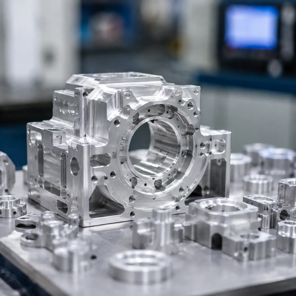
ZSCNC machines custom 6061-T6 aluminum plates, brackets, housings and related parts to approved drawings for packaging equipment OEMs. Our Wuxi machining base focuses on CNC milling and turning. Send part numbers, drawing revisions and quantities for a batch feasibility review.
Made to Customer Drawings and CAD Models
Provide a dimensioned PDF drawing and a matching STEP model where available. Identify the controlling document if they differ. Confirm native CAD or other file formats before transfer. Specify functional tolerances, datums, thread details and the finished condition; no universal tolerance applies to every feature.
Prototype, Replacement and Batch Production
State the sample quantity, quantity per production release and estimated annual demand. For replacement parts, provide the approved nominal drawing and mating-interface details. A worn sample does not by itself establish the original dimensions or assembly fit.
Why 6061-T6 Is Used for Packaging Machine Components
Strength-to-Weight Balance for Machine Components
6061 is considered for machined machine components where mass, strength and process requirements suit the design. Specify the alloy, temper and stock form on the drawing. Do not use one typical strength value as the acceptance requirement for every stock size or product form.
Machinability for Complex CNC Features
Review pockets, bores, mounting patterns and access for tooling against the complete geometry. Thin walls and deep features require a specific route review; no minimum wall thickness or cost saving is promised for every part.
Corrosion Resistance for Appropriate Machine Environments
Provide cleaning agents, concentration, temperature and exposure conditions before choosing material and finish. Neither bare 6061 nor anodizing establishes suitability for every washdown or product-contact environment. Related orders may specify hard-anodized 6061 aluminum parts; the coating and final fits still require review.
When Aluminum Is Preferred Over Stainless Steel
Compare the complete designs against loads, allowable deflection, moving mass, cleaning conditions and total order cost. A material substitution requires customer approval. Changing to aluminum alone does not guarantee faster machine cycles, smaller motors or longer service life.
6061 Aluminum Packaging Machine Parts We Machine
Send drawings for the components required by your packaging equipment design. Envelope, stock, feature access and order requirements are reviewed before quotation; the following groups describe parts for review, not guaranteed machine-level performance.
Mounting Plates, Brackets and Support Components
Provide datum faces, mounting patterns, thickness and load-related design limits for base plates, motor mounts and supports. Related anodized mounts and brackets require their own finish and final-fit specifications.
Housings, Covers and Machine Interfaces
Identify pockets, gasket grooves, mating faces and fastener access. If an enclosure needs a particular sealing or protection rating, state the equipment acceptance requirements; machining an O-ring groove alone does not establish that rating.
Sensor, Actuator and Automation Components
For sensor brackets, actuator mounts and end-effector components, provide mounting interfaces, adjustment needs and allowable movement. Alignment, vibration and handling performance require validation in the complete assembly.
Fixtures, Change Parts and Custom Machine Components
For guide plates, transfer blocks and fixtures, define contact surfaces, edge condition and locating relationships. List matched parts and format variants separately. See our machine-parts scope for related drawing-based components.
Complex Features in CNC-Machined 6061 Parts
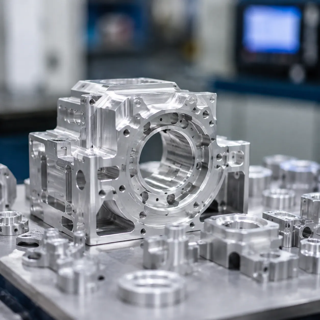
Highlight critical functional features on the drawing so that tool access, finishing and inspection can be reviewed before production.
Deep Pockets and Milled Profiles
Specify pocket depths, internal radii, floor thickness and surface requirements. Cutter reach and workholding depend on the complete geometry; any proposed radius or feature change requires customer approval.
Bores, Fits and Bearing Features
Specify bearing-seat and locating-hole size limits separately from positional requirements. Provide the mating-part specification and intended assembly method. Fit classes and numerical limits follow the approved drawing, nominal size and applicable standard; H6, H7 or a fixed 0.005 mm limit is not applied to every bore.
Threads, Counterbores and Mounting Hole Patterns
Provide thread standard, class, depth and any insert details, along with counterbore dimensions and hole-position requirements. Tooling and setup methods are selected after reviewing access and the material; thread milling or form tapping is not assumed for every hole.
Thin Walls and Weight-Reduction Features
Identify wall thickness, unsupported spans, pocket depths and permissible distortion. Confirm how the finished part will be supported or restrained during acceptance checks. Feasibility is reviewed for the actual geometry rather than a universal 1.0 mm wall capability.
Multi-Sided Features and Tool-Access Review
ZSCNC has no in-house five-axis machining, EDM or wire cutting. Angled faces, undercuts and multi-sided features require a tooling and setup review before quotation. Any proposed drawing change needs customer approval; a single clamping operation is not assumed.
Dimensional Control in 6061-T6 CNC Machining
Datum Strategy and Critical Feature Relationships
Define the locating faces, datum features and critical relationships between bores, mounting holes and mating surfaces. Agree the applicable drawing standard and inspection condition before machining. A common datum scheme supports consistent interpretation; it does not eliminate all assembly variation.
Controlling Distortion in Thin-Wall Aluminum Parts
Review stock condition, material removal, clamping and finishing stages for large or thin features. Specify whether acceptance applies in the free state or under defined restraint. No process is described as eliminating all distortion, and stress-relief treatment is not included by default.
Managing Critical Dimensions Through Multiple Operations
The machining route must preserve the specified feature relationships across setups. Equipment, fixturing and checking methods are confirmed for the order; automated spindle probing, zero-point fixtures and a temperature-controlled shop are not assumed capabilities.
Surface Finishing for 6061 Aluminum Machine Parts
Anodizing and Customer-Specified Finishes
State the coating specification, type, thickness, color, sealing and appearance requirements in the RFQ. Other finishing processes require confirmation. Do not assume a particular HRC value, cleaning resistance or electrical-contact performance from the finish name alone.
Protecting Critical Fits and Threads During Finishing
Mark surfaces that must remain uncoated, including any bores, threads, grounding contacts or datum faces. Agree masking boundaries and permissible contact marks. Define whether functional dimensions and thread acceptance apply before or after finishing.
Dimensional Considerations Before and After Anodizing
Anodizing and its preparation steps can change finished dimensions. Growth depends on the alloy and process conditions; a universal machining offset is not appropriate for every part. Confirm thickness, preparation, masking and final acceptance with the finishing route before setting machining allowances.
- Coated bores: Review the required final diameter and allowance with the mating part and finishing process.
- External fits: Review final size after treatment and distinguish coated from masked surfaces.
- Final checks: Specify the finished features to inspect and the required coating evidence.
The Aluminum Anodizers Council FAQ explains why alloy, process conditions and pretreatment affect dimensional change. The approved drawing and confirmed finish route govern each order.
Prototype and Batch Production of 6061 Aluminum Parts
For packaging OEM batches, identify each part number, revision, material condition and required finish. List sample quantity, quantity per release and anticipated annual demand separately. Indicate left/right variants and whether the order is counted in pieces or complete machine kits.
Prototype and First-Article Manufacturing
Agree the approval-sample quantity, dimensions to report, material documents and any customer assembly trial. Confirm the accepted revision before releasing production. A dimensional report and an equipment trial provide different evidence; specify both when needed.
Repeatable Workholding for Batch CNC Production
Fixturing and setup requirements are reviewed for the geometry and batch size. Include any matched-component or paired-plate requirements and the reference features that must remain consistent. No fixed fixture system or zero variation is promised.
In-Process Inspection and Batch Consistency
Agree critical dimensions, checking stages and reporting coverage before order acceptance. CMM, optical or other measurement requirements are confirmed for the geometry and order rather than included automatically.
Repeat Orders for Packaging Equipment Manufacturers
Reference the approved drawing, material, finishing and inspection requirements on repeat releases. Flag changes to mating parts or machine versions. Availability of material documents, retained setup records and phased delivery must be confirmed in the quotation.
Inspection of Custom 6061 Aluminum CNC Parts

Identify critical features and required report coverage before production. See our quality inspection scope. Inspection checks drawing requirements; it does not by itself establish machine performance or adjustment-free installation.
Critical Dimensions, Bores and Fits
Specify final bore sizes, fit limits, slot widths and mating dimensions. Agree access, measurement conditions and appropriate methods for the required limits. There is no fixed tolerance or equipment list for every 6061 part.
Datum and Geometric Feature Verification
Define datums and the applicable flatness, parallelism, perpendicularity or positional controls on the drawing. Agree how large or thin parts are supported during inspection and whether the features are checked after finishing.
Thread and Mounting Feature Inspection
Provide thread standard, class, depth and insert requirements. Agree checking criteria for threads, counterbores and countersinks, including whether they apply after coating or masking.
Inspection to Customer Drawing Requirements
Request first-article records, dimensional reports, material documents and coating evidence in the RFQ. Availability and coverage are confirmed for the order. Full CMM documentation and complete material traceability are not automatic inclusions.
Ordering Custom 6061 Aluminum Parts from ZSCNC
What to Include in Your RFQ
- Dimensioned PDF drawing and a matching STEP model, with the same part number and revision.
- 6061-T6 stock requirements, material specification and required documents.
- Critical datums, bores, fits, threads, thin-wall features and final acceptance condition.
- Coating specification, thickness, masking, color and appearance acceptance.
- Sample quantity, quantity per release, expected annual demand and required dates.
- Required inspection records, protective packaging and delivery destination.
STEP Model, Drawing, Quantity and Material Temper
Confirm which file controls if drawing and model differ. List each left/right variant and whether the quantity is pieces, pairs or complete kits. Material substitutions or drawing changes require approval before machining. Related aluminum material options must be reviewed for the actual design.
Surface Finish and Inspection Requirements
Agree finished dimensions, coating and inspection scope before order acceptance. Additional processes and document availability are confirmed in the quotation; see our surface-finishing information.
Batch Quotation and Drawing Review
Upload 6061 packaging-part drawings for a batch quotation. The form accepts PDF, STEP and DWG up to 5 MB per file; email info@zscncpack.com for larger files or other formats. Feasibility, price and lead time follow the confirmed material, machining, finishing and inspection requirements. The OEM validates the complete assembly.
Material and Finishing References
Use the specified stock and finishing requirements for order acceptance. The following general references support review; they do not certify ZSCNC parts or establish performance for a customer design.
- Aluminum Anodizers Council: anodizing FAQ and dimensional considerations
- Hydro: 6061 alloy data for extruded products — product-form data, not a universal requirement for every machined part.