Why Thin-Wall 6061 Aluminum Parts Are Difficult to Machine Accurately
Machining 6061 aluminum provides an ideal balance of strength, lightweight performance, and corrosion resistance. However, maintaining tight tolerances becomes complex when executing designs with thin features. As mass is removed, structural integrity drops rapidly, making thin wall aluminum CNC machining prone to physical deflection, chatter, and dimensional instability.
Low Structural Rigidity After Material Removal
Raw 6061 aluminum stock provides excellent stability. Once the cutting tool hollows out the workpiece, structural stiffness decreases exponentially relative to the remaining wall thickness.
- Flexibility under load: Walls thinner than 1.5 mm (0.060 in) lose self-supporting rigidity, flexing under normal cutter engagement rather than shearing cleanly.
- Loss of bulk support: Removing internal core material removes the structural foundation that stabilizes the outer geometry.
- Amplified variations: Reduced stiffness magnifies minor tool pressure changes, leading to unpredictable aluminum part deformation.
How Cutting Forces Can Deflect Thin Walls
During 6061 aluminum machining, end mills apply radial (side) and axial forces directly against the workpiece. On flexible geometry, these dynamic forces push thin features away from the intended tool path.
| Force Type | Impact on Thin Features | Resulting Dimensional Deflection |
|---|---|---|
| Radial Force | Pushes thin walls sideways away from the cutter. | Creates wall tapering, uneven thickness, and chatter marks. |
| Axial Force | Pulls or compresses unsupported features vertically. | Causes floor warping and inaccurate z-axis depth. |
| Harmonic Force | Triggers high-frequency tool chatter against thin features. | Compromises surface finish and causes tool wear. |
Why Deep Pockets Increase Distortion Risk
Deep pocket milling combined with thin walls multiplies manufacturing difficulty. Deep cavities demand longer tool reach, decreasing tool rigidity while simultaneously stripping away stabilizing stock mass.
- Tool overhang: Extended end mills deflect under cutting loads, distorting the vertical profile of the wall.
- Internal stress release: Deep pocketing rapidly liberates internal mill stresses inherent in 6061 stock, causing thin surrounding walls to twist or bow.
- Heat trapping: Coolant flow decreases deep inside pockets, causing localized heat buildup that triggers thermal expansion and aluminum machining distortion.
sensitive to structural changes, making precise machining a delicate balancing act. When we produce light, high-precision components, four primary factors trigger dimensional instability during the milling process.
Residual Stress in Aluminum Stock
Raw stock carries internal mechanical tension created during rolling, quenching, or extrusion processes. Even stress-relieved temper grades retain baseline internal forces locked deep within the grain structure.
- Trapped Forces: Standard mill operations create non-uniform stress profiles across bar or plate thickness.
- Material Sensitivity: Raw 6061 aluminum machining stock contains balanced internal tension that remains stable until cutting breaks the outer skin.
Stress Redistribution During Material Removal
As CNC cutters strip away material to form thin walls, internal structural equilibrium breaks down. Removing outer layers forces the remaining material to rebalance its internal forces, causing aluminum machining distortion like twisting or bowing.
| Machining Action | Internal Stress Reaction | Resulting Deflection |
|---|---|---|
| Single-sided heavy milling | Unbalanced surface stress release | Wall bows away from the cut side |
| Deep pocketing | Asymmetrical structural thinning | Twisting or cupping across the floor |
| Symmetrical light finishing | Balanced stress relief across both sides | High dimensional stability |
Clamping Force and Workholding Deformation
Standard vise jaws or aggressive fixtures easily overpower thin features. Squeezing a delicate workpiece forces elastic compression while the part is locked in place.
- Mechanical Squeeze: Clamping pressure flexes thin walls inward during active machining cycles.
- In-Fixture Illusion: Features cut under heavy force measure accurately while clamped, but experience spring-back into an out-of-spec state once released.
- Over-Constraining: Clamping rigid sections adjacent to delicate walls induces localized warping across critical mounting faces.
Cutting Heat and Local Thermal Effects
6061 aluminum has a high thermal expansion rate. Friction at the cutting edge rapidly transfers heat into thin features, which lack the physical mass to dissipate thermal energy efficiently.
- Localized Expansion: Thermal spikes cause thin sections to expand outward into the cutter during active machining.
- Post-Cooling Drift: Once the cut finishes and the metal cools down, the wall shrinks, leaving features undersized or distorted.
- Coolant Management: Consistent flood coolant is critical to stabilize thermal expansion when machining high-precision custom 6061-T6 aluminum CNC parts.
Why a Part Can Change Shape After It Is Unclamped
Unclamping a thin-wall 6061 aluminum part often reveals sudden dimensional shifts. While the component appears perfectly within tolerance while bolted or clamped to the machine bed, releasing those external forces allows internal stresses to equalize, altering the part's shape.
In-Fixture Accuracy vs. Free-State Geometry
Achieving tight tolerances while a part is locked in a vise does not guarantee that same dimensional accuracy once it hits the inspection bench.
| Condition | In-Fixture State | Free-State Geometry |
|---|---|---|
| Mechanical Constraint | Forced straight by clamps, pins, or vise jaws | Zero external physical restraint |
| Measured Accuracy | Appears perfectly flat and aligned on the CNC bed | Shows true dimensions after stress release |
| Primary Distortion Factor | Masked clamping forces and tool deflection | Unbalanced residual stress and spring-back |
Elastic Recovery and Spring-Back in Thin Features
When we perform thin wall aluminum CNC machining, thin features act like small springs during the cutting process.
- Elastic Flexing: Cutting forces push thin walls outward during a pass; once the end mill clears the area, the material snaps back, leaving excess stock behind.
- Residual Stress Release: Raw 6061-T6 aluminum contains internal stresses from rolling and heat treatment. As we carve away material, these stresses redistribute, causing thin features to bow or twist.
- Geometrical Instability: Features with wall thicknesses under 1.5 mm lack the structural stiffness required to resist internal stress movement without proper stress-relieving strategies.
Why Excessive Clamping Force Can Create Measurement Errors
Over-tightening workholding equipment is one of the most common causes of aluminum machining distortion. Unlike heavy-duty steel components or rigid custom 17-4PH change parts for packaging machinery, thin-wall aluminum extrusions and plates easily distort under standard mechanical vise pressure.
- False In-Process Checks: Measuring a part while clamped squashes thin walls flat, producing false target dimensions on your CMM or micrometer.
- Post-Release Elastic Bounce: The moment vise pressure releases, compressed walls spring outward, instantly driving hole centers, wall parallelism, and flat surfaces out of spec.
- Smarter Workholding: We mitigate workholding deformation by utilizing soft jaws customized to the part contour, vacuum fixtures, or torque-controlled clamping systems that distribute force evenly.
Machining Strategies for Thin-Wall 6061 Aluminum Parts
Controlling aluminum machining distortion requires a proactive strategy before the end mill ever touches the stock. When we manufacture complex components—like high-precision custom anodized mounts and brackets—we adjust our toolpath planning to compensate for low structural rigidity during thin wall CNC machining.
Planning Roughing and Finishing Operations
Never attempt to finish a thin wall feature in a single pass. We separate the machining lifecycle into distinct phases to maintain high dimensional accuracy in 6061 aluminum machining:
- Heavy Roughing: Remove 80% to 90% of excess material across all pockets to unlock internal stresses.
- Stress Relief Pause: Unclamp or relax the part briefly so the stock can shift without binding.
- Semi-Finishing: Bring features close to final shape while correcting any initial warpage.
- Finishing: Take light, high-speed passes with sharp tooling to hit target tolerances.
Balancing Material Removal Around Critical Geometry
Machining one side of a 6061 aluminum block completely before touching the opposite side triggers severe bowing. We balance toolpaths symmetrically across critical geometry to prevent asymmetric stress distribution:
- Alternate Cavity Clearing: Pocket out opposite sides incrementally rather than plunging deep into a single side.
- Equalize Wall Removal: Cut opposing thin walls down in matching steps to balance residual wall tension.
- Concentric Toolpaths: Spiral outward from the center to maintain uniform heat and stress distribution.
Leaving Controlled Stock for Finishing
Leaving too little stock causes the cutting edge to rub and push the wall; leaving too much creates excess force that deflects the wall. We maintain strict stock allowances to safeguard part stability before the final finish pass.
| Operation Stage | Stock Allowance (Per Side) | Primary Goal | Tooling Strategy |
|---|---|---|---|
| Roughing | 0.80 mm – 1.20 mm | Rapid material removal | High-feed roughing end mill |
| Semi-Finishing | 0.20 mm – 0.30 mm | Geometry realignment | Standard 3-flute carbide end mill |
| Finishing | 0.05 mm – 0.10 mm | tolerance & surface finish | Sharp, polished DLC-coated end mill |
Using Appropriate Tool Engagement and Cutting Parameters
High lateral cutting forces directly cause thin walls to flex, chatter, and lose tolerance. In 6061-T6 CNC machining, we utilize high-speed machining (HSM) techniques with light radial stepovers to direct cutting forces axially down the spindle rather than laterally into unsupported walls.
- Low Radial Stepover ($A_e$): Keep radial engagement between 5% and 10% of the tool diameter to minimize lateral push.
- Increased Axial Depth ($A_p$): Utilize deeper axial cuts paired with light radial engagement to wear the flute evenly and keep wall deflection minimal.
- Optimized Surface Footage: Run high RPMs and aggressive feed rates to transfer generated heat directly into the chip rather than the workpiece.
Workholding Strategies for Controlling Aluminum Part Deformation
Workholding is the single most critical factor when machining thin wall aluminum CNC parts. Standard vise clamping often pinches or warps flexible 6061-T6 stock. We rely on specialized fixture techniques to keep parts flat, stable, and accurate throughout every cutting pass.
Supporting Thin Walls Without Over-Constraining the Part
Supporting delicate features requires solid contact without excessive mechanical force. Over-constraining creates internal stress that springs back the moment clamps are released.
- Vacuum Chucks: Distribute hold-down force evenly across thin floors without applying mechanical side pressure.
- Custom Soft Jaws: Machined to match the exact profile of the workpiece, backing up weak walls during finishing cuts.
- Stabilizing Fillers: Filling deep cavities with temporary rigid wax or soluble materials dampens vibration during high-speed milling.
Distributing Clamping Forces Across the Workpiece
Concentrated clamp pressure pinches thin walls and distorts key dimensions. Spreading workholding loads preserves structural integrity.
| Workholding Method | Load Distribution | Primary Application |
|---|---|---|
| Standard Vise Jaws | Concentrated / High | Heavy roughing on solid block stock |
| Toe Clamps & Straps | Moderate / Edge-focused | Large flat aluminum plates |
| Custom Vacuum Fixtures | Uniform / Low-pressure | Ultra-thin floors and delicate walls |
| Hydraulic Swing Clamps | Consistent / Regulated | High-volume batch production runs |
Using Datum Features for Repeatable Repositioning
Accurate 6061 aluminum machining relies on solid reference points established early in the process to control aluminum part deformation across multiple operations.
- Precision Dowel Pins: Lock in repeatable X/Y positioning across multiple clamp setups.
- Machined Datum Pads: Provide flat, rigid surfaces to seat the workpiece correctly without flexing.
- In-Process Probing: Verifies datum locations before executing tight-tolerance finishing passes.
Why Fixture Design Depends on Part Geometry
No single fixture design fits every geometry. Asymmetric pockets, deep ribs, and curved profiles demand custom-engineered workholding solutions. For complex components, such as high-precision 5-axis thermoforming tool inserts for packaging machines, custom-contoured vacuum or mechanical fixtures are essential to maintain strict dimensional accuracy without twisting thin aluminum walls under tool load.
How Deep Pockets and Thin Floors Affect CNC Accuracy
Machining deep pockets with thin floors creates significant challenges for 6061 aluminum machining. As material is carved away, the remaining structure loses structural stiffness, making both the workpiece features and the cutting tool far more prone to bending under cutting forces.
Tool Deflection in Deep Machining
Reaching deep into a cavity requires longer end mills, which drastically reduces tool rigidity. Increased stickout amplifies cutting forces, leading to tool deflection during thin wall aluminum CNC machining.
- Tapered Pocket Walls: As end mills push away from the material, they cut less than planned at the bottom, leaving walls tapered rather than straight.
- Surface Chatter: The loss of cutter stiffness causes harmonic vibration marks across deep wall faces.
- Dimensional Drift: Tool push-out fluctuates with changing chip loads, making tight tolerances difficult to maintain across deep geometry.
Floor and Wall Deflection During Finishing
Thin floors and unsupported walls push away under light tool pressure during final finishing passes, compromising dimensional accuracy.
- Wall Spring-Back: The wall flexes outward under the tool, then springs back once the tool passes, leaving unwanted material behind.
- Floor Bouncing: Thin pocket floors flex downward under axial cutting forces, resulting in inconsistent floor thickness and poor surface finishes.
- Localized Flex: Unbalanced cutting forces drive aluminum part deformation across adjacent features, disturbing overall state dimensions.
Managing Tool Access Without Excessive Tool Overhang
Controlling wall flex and tool deflection requires short tool reach and optimized cutting angles.
- Shortest Reach Possible: Always select tools with the lowest length-to-diameter ratio capable of clearing pocket depth.
- Tapered Shank Tooling: Use tapered or stepped shanks during deep pocket roughing to maximize cutter stiffness.
- Multi-Axis Approaches: Instead of relying on extra-long end mills on standard setups, utilizing advanced strategies like cam profile machining with 3+2 vs simultaneous 5-axis positioning allows us to tilt the part toward the spindle. This keeps tool overhang minimal while accessing deep pocket features cleanly during 6061-T6 CNC machining.
Dimensional Control in Batch CNC Aluminum Production
Scaling thin wall aluminum CNC machining from a single prototype to a multi-hundred-part production run requires strict process control. Without a repeatable process, small variations in clamping pressure or cutter wear can quickly cause part-to-part dimensional drift.
Maintaining Repeatable Workholding Between Parts
Consistent locating and clamping are essential when loading raw stock or semi-finished components into production fixtures.
- Torque-Controlled Clamping: We use pneumatic fixtures or calibrated torque wrenches to ensure every operator applies identical clamping force.
- Chip-Free Locating Surfaces: Automated high-pressure air blasts flush chips and debris off fixture datums before loading the next workpiece.
- Contoured Soft Jaws: Custom aluminum soft jaws spread clamping pressure evenly across delicate geometries to prevent permanent deformation.
Monitoring Tool Wear During Production Runs
As end mills wear, cutting forces rise rapidly. Elevated lateral push forces push thin aluminum walls away from the cutter, leading to wall thickness variations and chatter marks.
| Tool Condition | Cutting Pressure | Thermal Impact | Dimensional Effect on Thin Walls |
|---|---|---|---|
| Sharp Edge | Low | Minimal | Holds tight tolerances within ±0.01 mm |
| Moderate Wear | Increasing | Moderate | Causes subtle deflection and wall tapering |
| Severe Wear | High | Excessive | Triggers chatter, heat expansion, and out-of-spec dimensions |
Tracking cutter life using tool timers and power consumption monitors prevents unexpected tool failure, much like monitoring critical wear parts on production equipment to maintain consistent manufacturing output.
In-Process Inspection of Critical Features
Catching dimensional drift early keeps full production batches within spec without wasting material.
- On-Machine Spindle Probing: We measure thin-wall thicknesses while the part is still in the fixture to adjust tool offsets automatically.
- Go/No-Go Snap Gages: Floor operators verify wall dimensions immediately after the finishing pass.
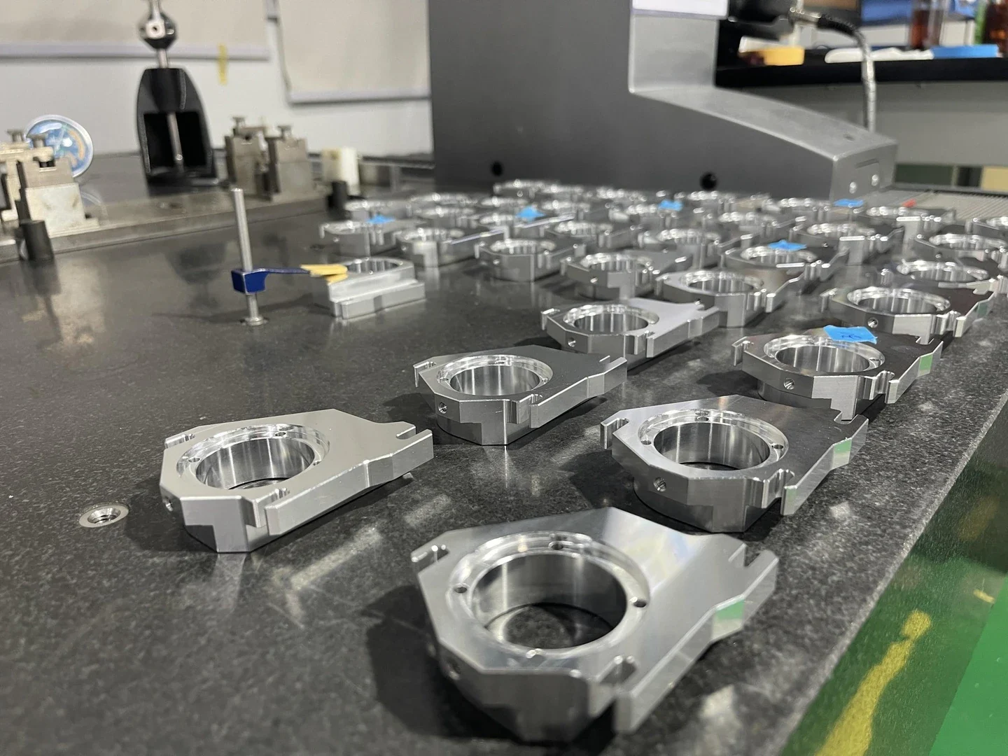
- Coordinate Measuring Machines (CMM): Unclamped free-state dimensions are checked in temperature-controlled environments to verify elastic recovery rates.
Controlling Variation Across Repeat Orders
To achieve identical 6061-T6 CNC machining results months apart, every step of the manufacturing setup must be locked in and documented.
- Standardized Material Sourcing: We source stress-relieved 6061-T6 plate from certified suppliers to keep residual stress levels consistent across material lots.
- Locked CAM Programs: Cutting speeds, feeds, stepovers, and toolpaths are archived so subsequent production runs execute exact cutting parameters.
- Dedicated Fixture Archives: Custom workholding jigs are tagged, stored, and periodically recalibrated to ensure dimensional accuracy aluminum machining remains repeatable for future orders.
Design and RFQ Considerations for Thin-Wall 6061 Parts
When submitting a Request for Quote (RFQ) for thin wall aluminum CNC machining, clear design specifications save lead time and prevent quality issues. Thin features react dynamically under cutting forces, so outlining explicit expectations upfront helps control aluminum machining distortion.
Identify Critical Dimensions and Datum Requirements
Thin-wall parts warp easily if datum points are poorly selected. Establishing clean reference features prevents part twisting during both cutting and post-process inspection. Implementing a reliable datum strategy for 5-axis sanitary flange adapters and similar thin-walled components ensures repeatable alignment across multiple operations without over-constraining fragile walls.
- Rigid Datums: Assign primary datums to solid bosses or thick bases rather than unreinforced thin webs.
- Restraint Conditions: Explicitly state whether critical dimensions apply in a free-state or clamped condition.
Distinguish Functional Tolerances From Non-Critical Features
Over-tolerancing flexible walls increases production costs and causes unnecessary rejections due to natural elastic spring-back. Reserving tight tolerances strictly for essential mating interfaces optimizes overall dimensional accuracy in aluminum machining.
| Feature Category | Recommended Tolerance | Production Impact on 6061 Aluminum |
|---|---|---|
| Critical Mating Surfaces | ±0.013 mm to ±0.025 mm | Requires specialized light-cut finishing and custom fixtures. |
| Non-Critical Thin Walls | ±0.100 mm to ±0.250 mm | Prevents stress buildup and significantly reduces scrap rates. |
| Minimum Wall Thickness | > 1.0 mm (Standard) | Avoids severe tool chatter and localized push-out deformation. |
Specify the Required Material Temper and Surface Finish
Raw material selection directly impacts stock stability during heavy material removal. Standard extruded stock retains stress that releases during milling.
- Material Temper: Specify 6061-T651 (stretcher-stressed) stock for high-aspect-ratio thin walls to minimize bowing after roughing.
- Surface Finish: Define realistic Ra values. Standard machined finishes (Ra 1.6–3.2 µm) eliminate unnecessary polishing steps that could thin or distort delicate wall geometries.
Provide a 3D Model and 2D Drawing for Critical Requirements
Supplying a complete digital package ensures accurate pricing and fast turnaround:
- 3D CAD File (STEP/IGES): Generates accurate CAM toolpaths and high-speed machining strategies.
- 2D Engineering Drawing (PDF): Defines GD&T callouts, tight tolerances, surface treatments, and inspection criteria that 3D files alone do not communicate.