zscncpack.com

How 5 Axis Toolpath Control Improves Thermoforming Accuracy

How 5 Axis Toolpath Control Improves Thermoforming Insert Accuracy for better setup reduction datum control and surface quality

Why Toolpath Control Matters for Thermoforming Insert Accuracy

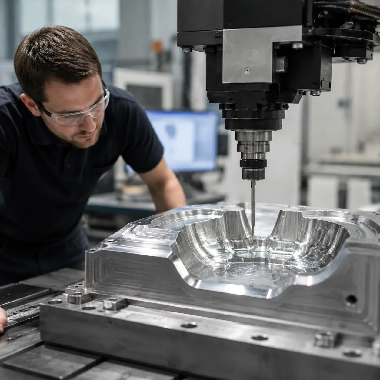
High-precision thermoforming inserts require exact surface geometry to ensure uniform plastic sheet stretching, clean part release, and consistent wall thickness. Precise 5-axis toolpath control dictates how the cutting tool interacts with the mold material, directly impacting final part fidelity and surface quality.

Complex Surfaces and Multi-Angle Features in Thermoforming Tooling

Modern thermoforming mold inserts frequently feature intricate geometries that present distinct machining challenges:

    • Compound Curves: Curved forming surfaces require smooth, continuous tool engagement to avoid ridges that telegraph onto thermoformed plastic parts.
    • Steep Draft Angles: Deep cavity sidewalls demand precise tool alignment to prevent cutter rubbing, vibration, and chatter marks.
    • Multi-Angle Vacuum Channels: Angled vacuum relief holes and venting features require accurate tool entry vectors across non-planar surfaces.

What 5-Axis Toolpath Control Actually Controls

Effective 5-axis CNC machining manages spatial position and tool orientation simultaneously throughout the cutting cycle.

Control ParameterFunction in MachiningImpact on Insert Accuracy
Tool Axis OrientationControls cutter tilt (A/B/C axes) relative to the workpiece surfacePrevents cutter deflection and maintains consistent cutting action.
Vector InterpolationSmooths transition angles between surface normal vectorsEliminates dwell marks, gouges, and sudden machine acceleration spikes.
Step-Over & Contact PointRegulates engagement location on the cutter tip or ball noseMaintains uniform 5-axis surface finish and scallop heights across complex contours.

Why 5-Axis Machining Does Not Automatically Guarantee Accuracy

Simply utilizing a 5-axis machine does not ensure a accurate thermoforming mold insert. Unoptimized programming creates severe quality issues:

    • Erratic Tilt Motion: Abrupt changes in tool orientation cause machine axis stutter, leaving localized gouges on critical sealing surfaces.
    • Excessive Tool Deflection: Improper tool orientation forces cutting with overly long tool overhangs, introducing dimensional drift on tight-tolerance features.
    • Inconsistent Surface Finish: Uncontrolled step-over distances during complex surface machining create uneven surface texture, negatively affecting sheet release during production.

How Fewer Setups Can Improve Feature Relationships

How 5-Axis Toolpath Control Improves Thermoforming Insert Accuracy

Executing a single setup machining strategy directly drives overall thermoforming insert accuracy by eliminating human error and mechanical shift between operations.

Reducing Repositioning of Complex Tool Inserts

When I switch from multi-step fixture repositioning to a single clamping cycle on 5-axis thermoforming tool inserts for packaging machines, I instantly remove tolerance stack-up risks.

    • Zero Alignment Drift: Eliminates micro-shifts caused by manual reclamping and indicator resetting.
    • Streamlined Production: Eliminates the need for expensive secondary tombstone fixtures and modular soft jaws.
    • Tighter Feature Location: Keeps angled vacuum passages aligned with high-precision forming surfaces.

Maintaining Datum Relationships Across Multiple Surfaces

Machining every side of a complex thermoforming mold insert from one baseline reference guarantees strict geometric dimensioning and tolerancing (GD&T).

    • Locked Reference Point: Primary datums stay fixed throughout the entire toolpath program.
    • True Position Accuracy: Keeps side-action slides, seal beads, and pocket walls tightly locked relative to each other.
    • Perfect Parting Lines: Prevents misaligned split lines that cause plastic web flash and trim issues during production thermoforming runs.

When 3-Axis Machining May Still Be Appropriate

While 5-axis toolpath control excels on dynamic geometries, standard setups remain a cost-effective choice for basic tool designs. Evaluating 3+2 vs simultaneous 5-axis machining options helps balance mold production costs against required accuracy levels.

Machining ApproachBest Fit GeometryKey Advantage
3-Axis MachiningFlat plates, shallow pockets, simple 2D planar profilesLower machine hourly rates and basic CAM setup
5-Axis Toolpath ControlDeep draft walls, multi-angled vacuum ports, steep contoursSingle-setup precision, shorter tool deflection, superior surface finish

How Tool Orientation Affects Complex Surface Machining

5-Axis Toolpath & Thermoforming Insert Accuracy 5-Axis Path Control for Thermoforming Inserts

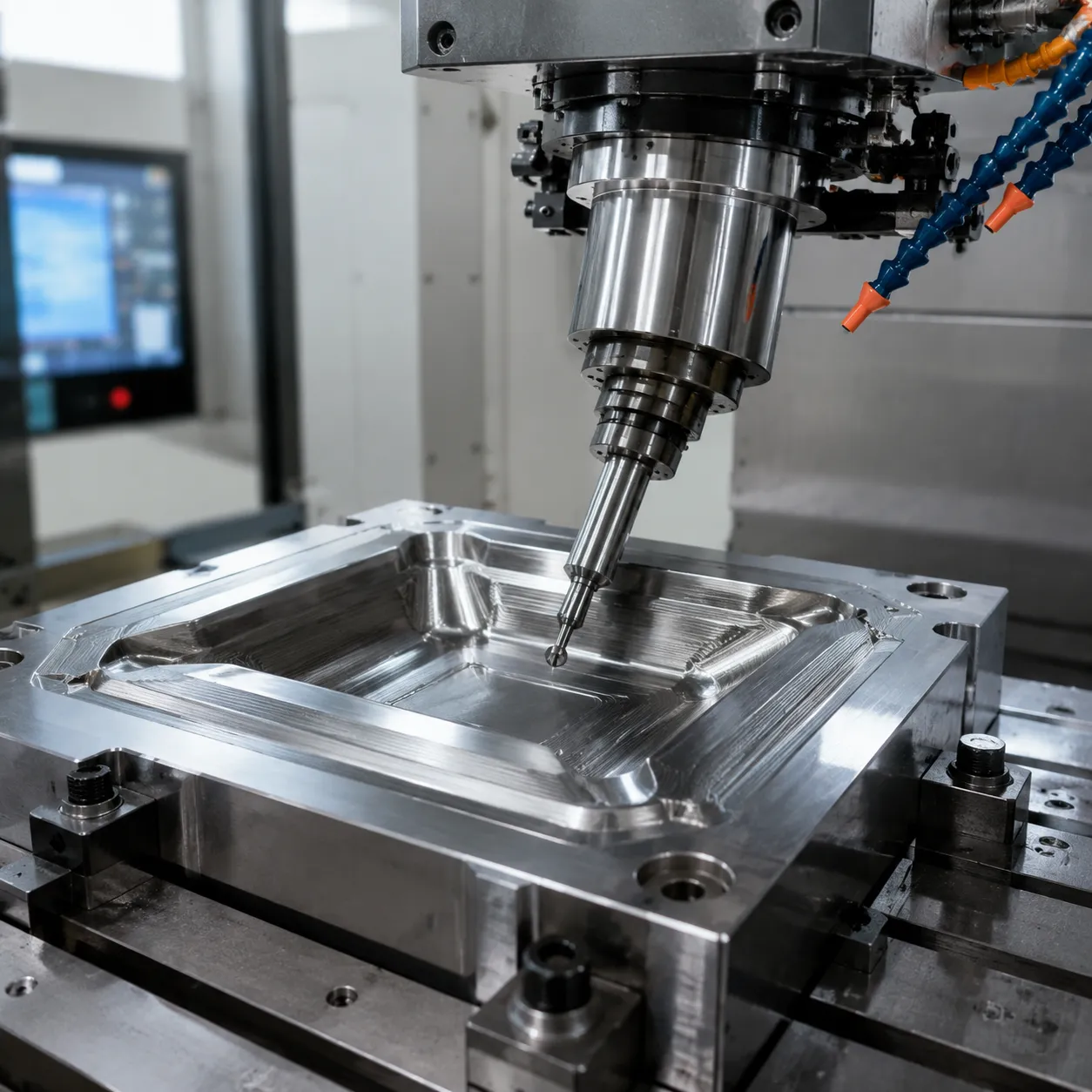
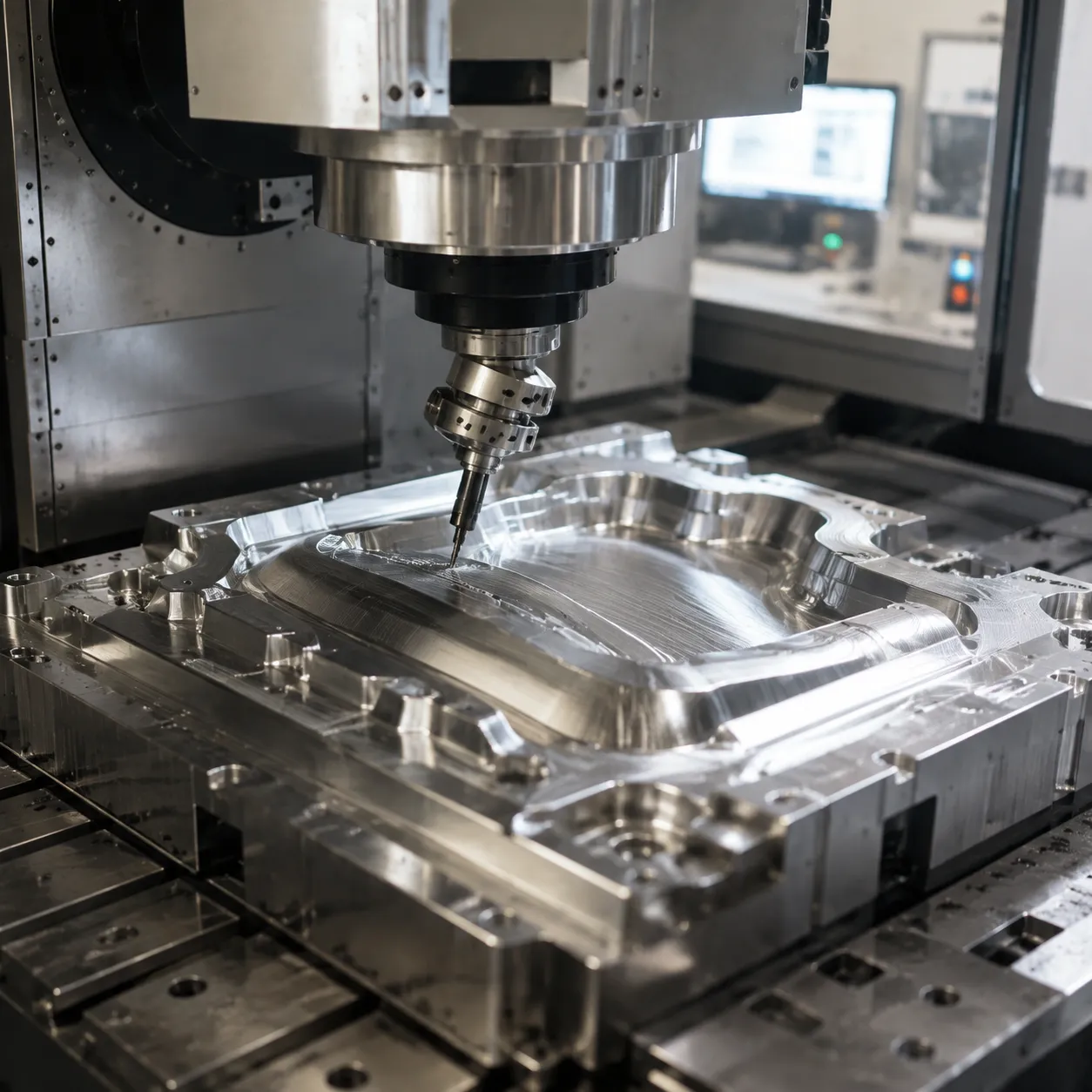
Controlling tool orientation during 5-axis CNC machining transforms how cutters interact with complex 3D mold geometry. By tilting the cutter relative to the part surface, we maintain an ideal contact angle across complex, freeform surfaces.

Maintaining Better Tool Access to Steep and Curved Surfaces

Fixed 3-axis setups force cutting tools to approach deep cavities and steep sidewalls vertically. Dynamic tool axis orientation continuously angles the spindle to reach tight radii, deep pockets, and draft angles without risking spindle collisions.

    • Improved Reach: Access deep mold cavities without using massive extension holders.
    • Optimal Cutting Angles: Keep the tool perpendicular or at a fixed lead/tilt angle to steep sidewalls.
    • Constant Engagement: Maintain stable material removal rates along draft angles and curved transitions.

Using Shorter Tools Where Geometry Allows

Tilting the workpiece or cutter clears body clearance obstacles. This allows us to run short, rigid tooling instead of long-reach end mills that vibrate and flex.

Tool ConfigurationRigidityDeflection RiskSurface Finish Impact
Short Stub Tools (5-Axis Tilting)HighMinimalSuperior micro-finish
Extended Reach Tools (3-Axis)LowHighVibration chatter marks

Reducing Tool Deflection on Difficult-to-Reach Features

Tool deflection directly ruins thermoforming insert accuracy, creating dimensional variations on deep walls and tall ribs. Using shorter tools through 5-axis toolpath control minimizes tool bending under load.

    • Dimensional Integrity: Holds tight tolerances on tall, thin mold cores and deep cavity walls.
    • Uniform Material Allowance: Leaves consistent stock for finishing passes, preventing cutter chatter.
    • Extended Tool Life: Reduces uneven wear caused by tool flexing and vibration.

Controlling Tool Contact on Contoured Forming Surfaces

When 3-axis ball-nose end mills machine flat or shallow surfaces, the center tip cuts at zero surface speed, dragging material rather than shearing it. Achieving an optimal 5-axis surface finish requires tilting the cutter to keep the sweet spot of the tool radius engaged with the material.

    • Eliminates Zero-Velocity Center Point: Shifts contact away from the dead-center tip to maintain effective cutting speed.
    • Reduces Scallop Heights: Allows larger step-overs while maintaining smooth, hand-polish-free mold faces.
    • Consistent Shearing Action: Delivers a uniform surface texture across all contoured forming surfaces on the thermoforming mold insert.

Toolpath Factors That Affect Thermoforming Insert Quality

5-Axis Toolpath Factors for Thermoforming Insert Quality

When we program a thermoforming mold insert, generating a viable toolpath involves far more than simply converting 3D CAD geometry into machine code. Specific programming variables directly govern thermoforming insert accuracy, surface texture, and dimensional repeatability across complex cavities.

Tool Axis Orientation and Tilt Strategy

Maintaining optimal tool axis orientation prevents cutting with the center tip of a ball-nose end mill, where cutting velocity drops to zero.

    • Lead and Lag Angles: Tilting the cutter 10° to 15° relative to the surface normal ensures contact occurs on the tool's active cutting edge rather than pushing material.
    • Consistent Surface Speed: Proper tilt strategies stabilize cutting forces and eliminate surface smearing on aluminum or tool steel inserts.
    • Predictable Pressure: Continuous multi-axis orientation keeps tool pressure stable, preventing sudden spikes during complex surface machining.

Step-Over and Surface Scallop Considerations

Achieving a superior 5-axis surface finish requires balancing step-over distance with cycle efficiency. In thermoforming tooling, surface scallops transfer directly onto plastic sheets during vacuum forming.

Scallop FactorFixed-Axis Capability5-Axis Toolpath ControlImpact on Insert Quality
Effective Tool RadiusFixed to physical cutter radiusEmploys barrel or large-radius contact anglesDrastically lowers scallop height
Pass DensityRequires tight step-oversPermits wider step-oversReduces cycle time while improving finish
Post-ProcessingHeavy hand polishing neededMinimal bench work requiredPreserves true CAD dimensions

Feed, Acceleration and Smooth Machine Motion

Maintaining a constant chip load during 5-axis CNC machining depends heavily on how the machine controller executes dynamic motion across multiple axes.

    • Vector Smoothing: Advanced toolpath algorithms smooth out sharp angular transitions, preventing micro-gouges along cavity walls.
    • Look-Ahead Processing: High-speed controllers read ahead to maintain steady feed rates through tight transition radii.
    • Vibration Suppression: Fluid velocity motion eliminates chatter marks that ruin forming surfaces and compromise airflow channels.

Collision Avoidance and Toolholder Clearance

Automated 5-axis toolpath control allows tool tilting to clear high cavity walls while keeping tool stick-out to an absolute minimum. Using shorter cutters significantly reduces tool deflection, ensuring steep draft angles and deep features remain dimensionally true without risk of toolholder collision.

Critical Thermoforming Features That Benefit From Controlled Toolpaths

Precise 5-axis toolpath control directly impacts the functional areas of a thermoforming mold insert. By continuously steering the cutter relative to the part geometry, we lock in strict tolerances on high-impact features that dictate final part quality.

Contoured Forming Cavities and Profiles

Complex, multi-sided cavities require constant vector adjustment to maintain consistent surface contact. Continuous 5-axis CNC machining eliminates localized tool chatter and faceted surfaces on deep-draw pockets, ensuring uniform sheet contact and consistent wall thickness during vacuum forming.

Radii and Transition Surfaces

Tight corner radii and organic transition zones frequently suffer from tool deflection or gouging in conventional setups. Dynamic tool tilt strategies keep the cutter in its optimal contact zone, yielding smooth surface scallops without manual benching steps that distort thermoforming insert accuracy.

Angled Vacuum Holes and Air-Flow Features

Molds rely on complex air evacuation networks to pull hot plastic tight against the tool. Drilling compound-angled vacuum vents in the same setup as the primary cavity keeps hole positions exact. When integrating these features alongside custom anodized mounts and brackets for OEM packaging, exact hole alignment ensures uniform air evacuation across every single cycle.

Datum and Mounting Interfaces

Machining mounting pockets, alignment pin locations, and side datums in a single setup preserves their true geometric relationship to the active forming surfaces. This guarantees that replacement inserts drop directly into master base plates without tedious hand-fitting or shimming.

Thermoforming Feature5-Axis Toolpath StrategyAccuracy & Quality Benefit
Complex CavitiesConstant surface contact vectoringPrevents chatter; standardizes plastic wall thickness
Organic RadiiLead/lag angle tilt controlEliminates hand-polishing and preserves surface tolerances
Angled Vacuum VentsFixed-vector multi-axis drillingEnsures precise air evacuation with zero burr buildup
Mounting DatumsSingle setup multi-side millingMaintains true positional tolerance to the mold base

Why Machining Strategy Alone Is Not Enough

A perfect 5-axis toolpath control strategy is only half the battle. While optimized CAM programming dictates the ideal cutter motion, physical machine conditions dictate the actual outcome. To achieve true thermoforming insert accuracy, programming must be backed by rigorous physical control on the shop floor.

Machine Calibration and Geometric Accuracy

Even the most sophisticated software cannot compensate for mechanical misalignment. In multi-axis manufacturing, minor volumetric errors or rotary axis pivot shifts compound rapidly.

    • Kinematic Center Errors: Misalignment in the A or C axis pivot points directly skews multi-sided features.
    • Axis Squareness: Non-orthogonal linear axes distort 3D mold profiles.
    • Regular Calibration: Maintaining strict laser calibration and ballbar testing on our advanced 5-axis machining capabilities ensures the machine executes CAM instructions flawlessly.

Workholding and Datum Control

A thermoforming mold insert subjected to heavy multi-axis cutting forces will shift if workholding lacks rigidity.

    • Rigid Clamping: Minimizes part movement and dampens vibration during high-speed directional changes.
    • Zero-Point Systems: Ensures rapid, precise positioning without introducing alignment errors.
    • Datum Alignment: Applying a reliable datum strategy for 5-axis machining guarantees that physical reference points match digital CAM coordinates across every tilt angle.

Tool Condition and Cutting Stability

Cutter degradation quickly compromises complex tool surfaces regardless of toolpath quality.

    • Tool Runout: Concentricity errors greater than 0.005 mm destroy tight tolerances and leave uneven step-overs.
    • Cutting Edge Wear: Worn end mills increase cutting pressure, causing tool deflection on steep cavity walls.
    • Vibration and Chatter: Dynamic instability ruins surface finishes, requiring extra manual polishing that destroys dimensional accuracy.

Thermal Effects During Long Machining Cycles

Intricate thermoforming tooling often requires extended cycle times. Spindle heat and shop floor ambient shifts induce physical expansion across both the machine structure and the workpiece. Active thermal compensation and controlled coolant temperatures are essential to prevent dimensional drift over long finishing passes.

How to Verify a 5-Axis Thermoforming Insert After Machining

Validating thermoforming insert accuracy requires systematic post-machining verification to confirm that 5-axis toolpath control delivered exact geometry and tight tolerances. We rely on a structured inspection process to audit critical features before tooling integration.

Verification StageTarget FeaturesPrimary Inspection Tool
Datum & MountingBase planes, alignment dowels, bolt patternsCMM touch probing
Critical Profiles3D cavity contours, radii, transition zones3D optical scanning & CAD overlay
Vacuum HolesCompound-angle vent positions & entry/exit pointsPin gauges & vision systems
Surface FinishForming cavities, seal borders, scallop heightsProfilometer (Ra measurement)

Checking Datum and Mounting Features

We verify primary datum faces and mounting interfaces first to establish an accurate coordinate reference system:
Flatness and Parallelism: Probe base surfaces to prevent stress or distortion when bolting the thermoforming mold insert into the main tool block.
Location Tolerances: Check dowel hole positions and thread centers using CMM probing to guarantee repeatable positioning across multi-cavity layouts.

Verifying Critical Profiles and Dimensions

Complex surfaces cut via 5-axis thermoforming machining require continuous profile validation across non-planar geometries:
Point-Cloud Comparison: Overlay 3D laser scan data directly against the native CAD file to detect profile deviations caused by tool deflection or cutter wear.
Wall Angle & Depth Checks: Verify draft angles and cavity depth consistency to eliminate drag marks or part distortion during thermoforming.

Inspecting Vacuum Hole Position and Orientation

Angled vent holes machined during single setup machining must be clear and precisely aligned:
Breakout Position: Confirm that compound-angle air holes break through cleanly in internal radii and deep pockets where trapped air forms bubbles.
Passage Integrity: Inspect internal air channels for burrs or remaining chips to guarantee unobstructed airflow during production cycles.

Checking Surface Finish Where Specified

Maintaining uniform surface texture prevents visual defects from transferring onto warm plastic sheet material:
Scallop Height Audit: Measure peak-to-valley roughness across steep walls and transitions to verify optimal tool step-over settings.
Texture Consistency: Measure surface roughness to confirm the engineered surface finish meets specification, ensuring smooth part release and defect-free optical clarity.

When 5-Axis Machining Makes Sense for Thermoforming Tooling

While 3-axis machining works well for simple plates, adopting 5-axis toolpath control becomes critical when part complexity demands higher thermoforming insert accuracy. We apply 5-axis CNC machining when conventional setups compromise precision, surface quality, or production lead times.

Complex Packaging Tool Geometry

Modern thermoforming packaging molds feature intricate draft angles, compound radii, and continuous freeform surfaces. Advanced 5-axis surface machining keeps the tool perpendicular to complex contours, drastically improving surface finish and maintaining tight tolerances.

    • Organic Contours: Achieves uniform material removal across complex 3D shapes without manual hand polishing.
    • Deep Pockets & Draw Depths: Allows tool axis orientation adjustments so shorter, stiffer tools can reach deep features without tool deflection.

Multi-Sided Features Requiring Multiple Conventional Setups

Relocating a thermoforming mold insert across multiple 3-axis setups introduces stack-up tolerances and alignment errors. Utilizing single setup machining on a 5-axis platform locks all geometry into a single origin point.

Feature Metric3-Axis Multi-Setup Machining5-Axis Single Setup Machining
Setup Count3 to 5 repositionings1 unified setup
Datum ErrorHigh risk from re-clampingEliminated (fixed reference point)
Feature-to-Feature AccuracyDependent on operator precisionGuaranteed by machine kinematics
Lead TimeExtended due to fixture changesOptimized for rapid delivery

Consolidating operations into one continuous strategy ensures strict thermoforming tooling accuracy. For integrated tooling solutions, review our packaging machinery guide.

Replacement Inserts Made From Existing CAD and Tooling Drawings

When reproducing legacy mold inserts or manufacturing direct replacements from customer CAD files, 5-axis toolpath control replicates digital models with exact fidelity.

    • CAD-to-Part Repeatability: Translates complex toolpath strategies directly onto raw stock without geometric drift.
    • Plug-and-Play Fitment: Guarantees replacement inserts drop seamlessly into existing master mold bases without manual benching.
Scroll to Top