Are custom tooling costs and failed DFM checks delaying your packaging parts?
Unnecessary undercuts can increase CNC machining complexity by restricting cutter access, requiring special tools, additional setups, or alternative machining strategies. For packaging machine components, reviewing these features during DFM can help simplify production without changing the functional design intent.
In this guide, you're going to learn the exact Design for Manufacturability (DFM) strategies to eliminate undercuts, optimize tool access, and slash your manufacturing costs.
Let's dive right in!
Understanding CNC Undercuts in Packaging Part Designs
What Is a CNC Undercut in Packaging Inserts and Molds?
A CNC undercut is any recess, overhang, or internal pocket feature on a packaging part that standard straight-cutting tools cannot reach from a direct top-down orientation. When we engineer custom foam packaging, thermoform aluminum molds, or protective enclosures, undercuts happen whenever geometry blocks the straight vertical Z-axis path of a cutting tool.
If a cutter cannot maintain direct line-of-sight access along the primary tool access vector, standard milling bits leave un-machined material behind, ruining part tolerances.
Why Undercuts Cause Machining Errors in 3-Axis CNC Routing
Standard 3-axis CNC routing operates along three linear axes: X (side-to-side), Y (front-to-back), and Z (up-and-down). Because the spindle stays strictly vertical, side-recessed geometry presents major production bottlenecks.
- Tool Collisions: Pushing a standard end mill sideways into a recessed pocket forces the tool shank or collet to slam into upper part walls.
- Trapped Material: Vertical bits simply skip hidden overhangs, leaving uncut stock that prevents electronic devices or products from fitting into the final packaging.
- Severe Chatter and Tool Breakage: Forcing non-undercutting end mills into side pockets creates excessive lateral friction, leading to rough surface finishes and broken bits.
- Increased Setup Costs: Resolving unintended undercuts requires manual repositioning or extra fixturing, driving up machine hours and scrap rates.
Packaging Applications Most Vulnerable to Undercuts
Certain packaging designs trigger undercut issues far more frequently than others due to their functional retention needs and complex geometry.
| Packaging Application | Common Undercut Feature | Machining Impact |
|---|---|---|
| Custom Foam Inserts | Deep finger-pull cavities, side-retention slots, and bottom lip grooves | Tool shank friction tearing soft foam and incomplete cavity profiles |
| Thermoform Trays | Vertical 90° sidewalls, undercut locking ribs, and stacking shoulders | Mold geometry trapping vacuum sheets and preventing part ejection |
| Rigid Enclosures | Internal latch pockets, recessed hinges, and perimeter snap-fits | Blocked line-of-sight access for standard 3-axis milling bits |
Core Design Strategies to Eliminate CNC Undercuts
We eliminate CNC undercuts directly in CAD to prevent machining delays and lower overall production costs. By modifying part geometry before sending files to the mill, we keep production running smoothly on standard equipment.
Align Part Orientation with the Tool Access Vector
Rotating the part in CAD so features face the spindle directly removes hidden geometry. Aligning pockets and slots along a single primary tool access vector lets standard 3-axis CNC machines reach all features in a single setup, cutting down on extra fixturing.
Split Complex Geometries into Modular Assemblies
When a packaging component features overhangs on multiple sides, splitting it into modular sub-components solves tool access issues. When manufacturing high-performance custom precision change parts for packaging machines, modular designs allow us to mill each section using standard tooling before joining them with dowels, fasteners, or adhesives.
Reposition Parting Lines
Moving the parting line to the outermost contours or natural geometric breaks eliminates trapped recessed features. This adjustments prevents cutter obstruction in mold cavities without compromising part strength or seal integrity.
| Design Strategy | Core Action | Primary Benefit |
|---|---|---|
| Vector Alignment | Rotate CAD orientation to face spindle | Eliminates extra machine setups |
| Draft Angles | Taper vertical walls 1° to 3° | Provides cutter clearance & stops binding |
| Modular Splitting | Divide 1 complex part into 2 simple parts | Enables 3-axis milling across all faces |
| Parting Line Shift | Relocate mold split to outer edges | Removes overhangs in thermoform tooling |
Smart Tooling Alternatives When Undercuts Are Unavoidable
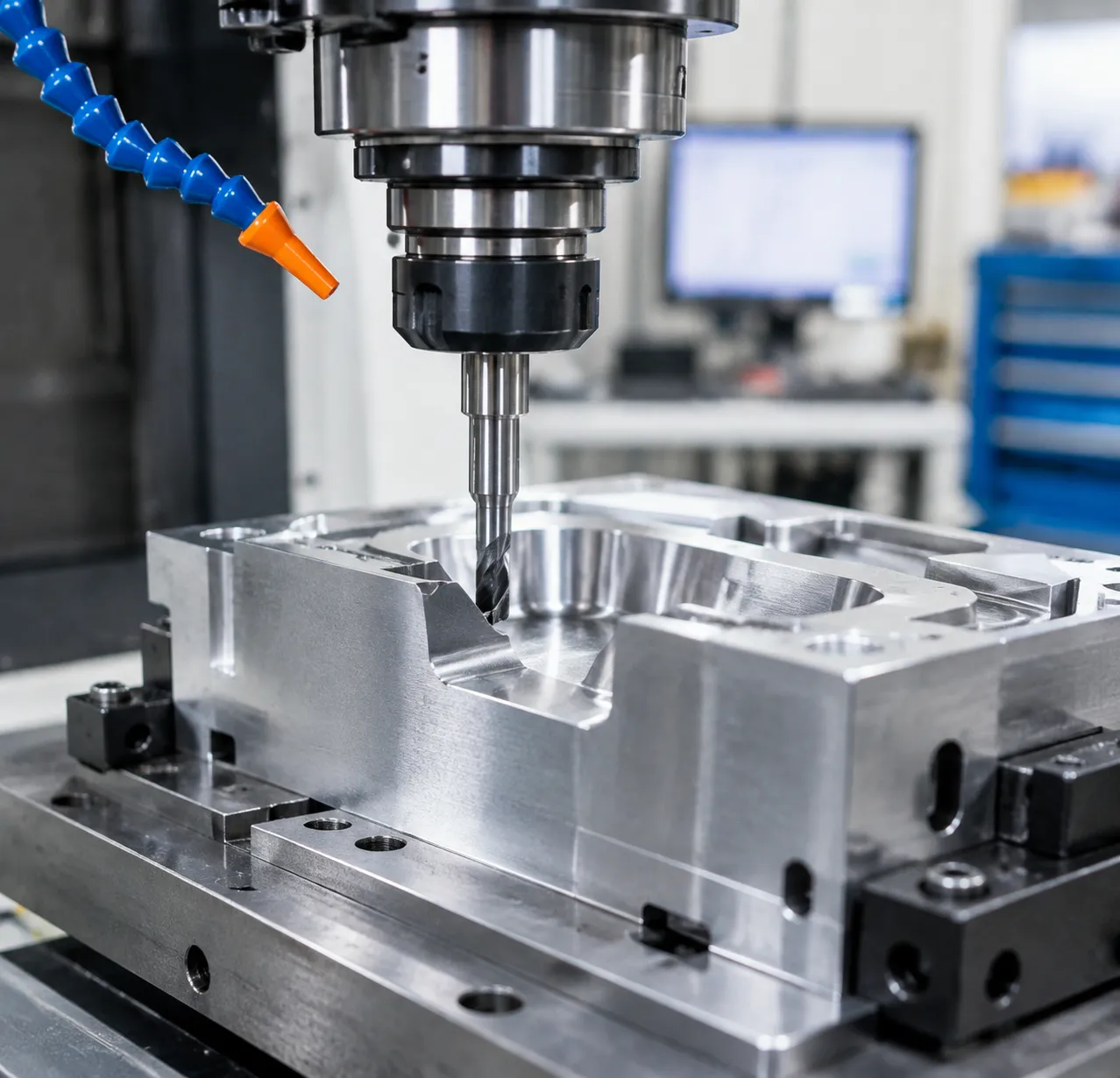
Sometimes a packaging part design demands an internal lip, dynamic snap-latch, or deep side groove that you simply cannot redesign out. When we run into trapped geometry that a straight vertical pass cannot reach, we pivot to specialized cutting tools and advanced multi-axis machine setups.
Specialized Cutters for Internal Features
When standard flat end mills fail to reach recessed areas, custom profile cutters allow us to machine behind obstruction walls without colliding with the workpiece:
- T-Slot Cutters: Ideal for cutting horizontal side channels, O-ring grooves, and rectangular retention slots in rigid enclosures or metal molds.
- Spherical (Lollipop) Mills: Perfect for 3D contoured undercuts, organic curves in custom foam packaging CNC routing, and multi-directional pocket clearing.
- Dovetail Bits: Essential for angled locking geometry, slide mechanism guides, and tapered snap-fit packaging latches.
| Tool Type | Best Packaging Application | Primary Advantage |
|---|---|---|
| T-Slot Cutters | Side grooves in rigid enclosures | Cuts flat internal channels without re-orienting the part |
| Lollipop Mills | Contoured foam packaging & mold cavities | Full 3D spherical access for tight internal radii |
| Dovetail Bits | Interlocking packaging trays & sliding latches | Precision angular side cuts in a single pass |
Multi-Axis Machining for Unrestricted Tool Access
When custom tooling hits physical reach limits, switching from traditional 3-axis routing to multi-axis setups expands our tool access vector. Tilting the spindle or rotating the part dynamically allows standard end mills to clear deep overhangs without requiring slow secondary manual setups.
For complex mold geometry, implementing 5-axis toolpath control for thermoforming accuracy allows us to maintain optimal cutter contact while tilting past restrictive walls. When evaluating machine strategies for complex packaging machine parts, comparing 3+2 vs simultaneous 5-axis machining helps us reduce cycle times while cleanly milling steep internal side walls.
Modifying Geometry for Standard End Mills
You do not always need expensive 5-axis machines or specialty bits to resolve hard-to-reach features. Minor CAD geometry tweaks often allow standard tooling to perform reliable undercut machining:
- Corner Reliefs (Dogbone Cuts): Add small circular relief breakouts at internal corner joints so rectangular mating parts seat fully without needing sharp internal corners.
- Expanded Corner Radii: Increase internal radii to fit larger, stiffer end mills. This eliminates chatter and reduces tool deflection during deep vertical passes.
- Tool Clearance Recesses: Machine shallow relief pockets adjacent to overhangs to ensure adequate CNC tool clearance for standard cutter shanks.
Design for Manufacturability (DFM) Workflow for Packaging Parts
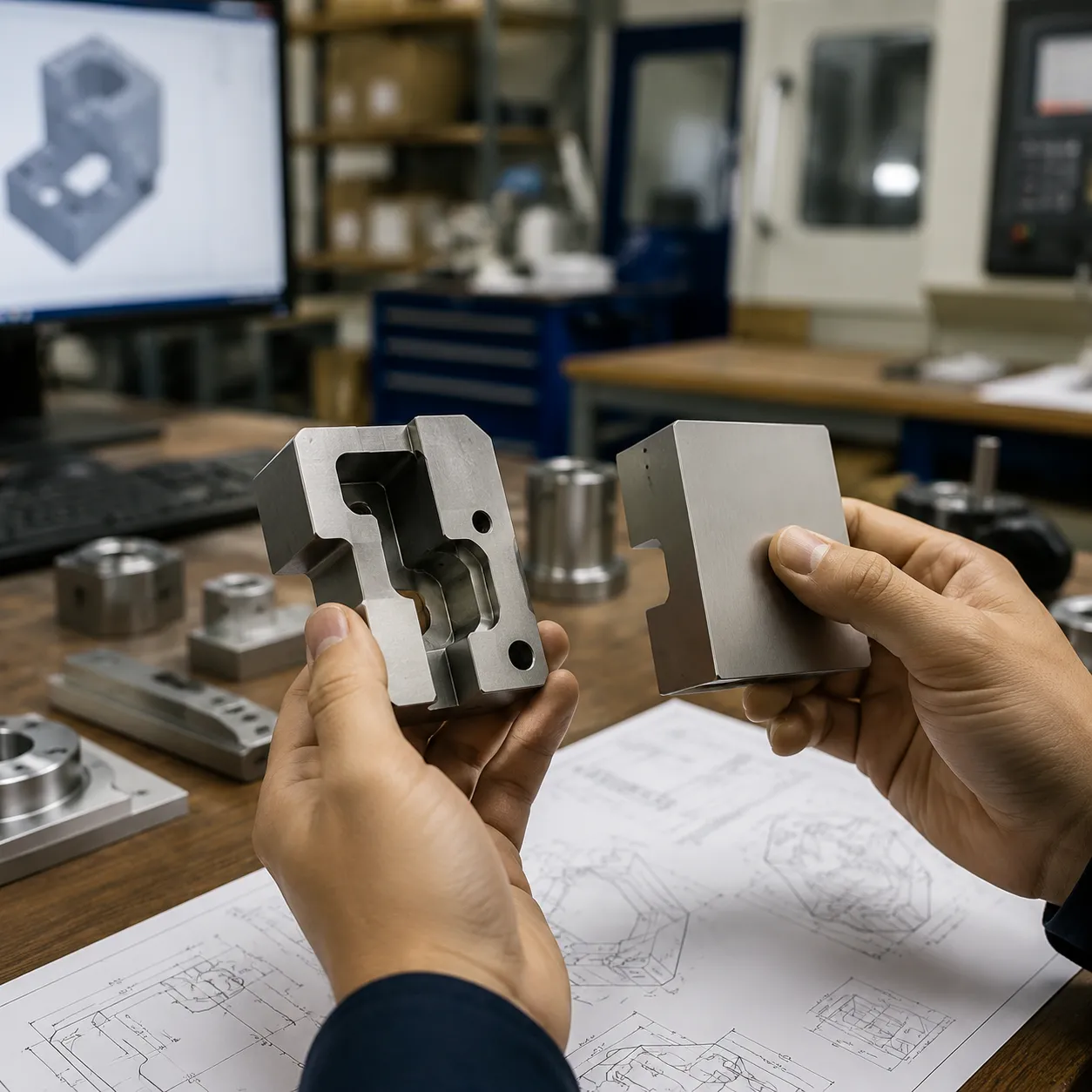
We integrate DFM for CNC machining at the very start of every project to catch geometry issues early and keep production lean.
Automated CAD Undercut Checks
Before sending any custom CNC parts to the shop floor, we run automated draft and undercut analysis in CAD to remove undercuts CAD models often hide. This instantly flags trapped faces, deep vertical walls, and obscured geometry along our target tool access vector. Catching these digital errors early prevents broken end mills and ruined stock. Utilizing DFM-optimized CNC machined plates ensures that pocket depths and wall clearance are ready for standard tooling from day one.
Balancing Part Protection and Machining Speed
Packaging inserts must hold items securely, but over-engineered retention features cause cycle times to skyrocket. We balance product protection with fast toolpath execution through targeted design tweaks:
| Design Feature | Protection Goal | DFM Adjustment | Cycle Time Impact |
|---|---|---|---|
| Deep retention pockets | Prevents product shift | Add 3° to 5° draft angles | 25% faster roughing passes |
| Snap-fit overhangs | Locks parts in place | Replace with split modular inserts | 30% reduction in milling time |
| Sharp inner corners | Fits outer box edges | Increase radii to match cutter diameter | Eliminates secondary tool swaps |
Cost Savings: Tooling Wear and Machine Hours
Stripping unnecessary undercuts from packaging designs delivers immediate cost reductions across production runs:
- Lower Tooling Expense: Eliminates the need for fragile lollipop cutters or specialized dovetail bits that wear out quickly.
- Machining Setup Reduction: Keeps jobs on standard 3-axis CNC routers by avoiding complex multi-axis re-fixturing.
- Maximized Feed Rates: Allows standard flat and ball-end mills to run at peak RPMs with optimal CNC tool clearance.
Frequently Asked Questions
Can standard 3-axis CNC machines cut undercuts on packaging parts?
Yes, but with strict geometric limits. Standard 3-axis CNC routing equipment moves strictly along the X, Y, and Z axes, meaning straight end mills cannot reach features shaded from the top tool access vector. We can machine basic horizontal undercuts on a 3-axis setup using specialty cutters like T-slot or dovetail bits. However, for complex 3D undercuts or angled relief features in custom foam packaging inserts, standard 3-axis setups require manual part flipping or multi-axis tooling updates.
How do draft angles affect the fit of foam and plastic packaging inserts?
Draft angles introduce a slight taper (typically 1° to 3°) along vertical walls to give tools clearance and ease part ejection:
- Thermoformed Plastics: Proper draft angles prevent hot sheets from sticking, dragging, or tearing against mold sidewalls during ejection.
- Custom Foam Inserts: Adding a subtle draft angle prevents router bits from pinching dense foam, creating clean edges and a reliable friction fit for protected products.
What is the easiest way to detect undercuts in CAD software?
The most efficient method is running an integrated CAD undercut analysis tool or color-coded draft analysis module before prototyping:
- Define Direction: Set the primary pull direction or tool access vector (typically the Z-axis).
- Color Mapping: The software instantly highlights trapped geometry, zero-draft walls, and negative overhangs in red or yellow.
- Evaluate: Identify problematic zones to determine whether a simple draft angle fix or a dedicated undercutting end mill is required.
Is it cheaper to redesign the packaging part or switch to 5-axis CNC milling?
Redesigning the part to eliminate undercuts is usually the most cost-effective path for high-volume manufacturing. Tweaking parting line placement or splitting complex parts into modular pieces keeps production on lower-cost 3-axis machines. However, for complex molds with tight tolerances where design changes aren't an option, using specialized 5-axis thermoforming tool inserts eliminates multi-setup re-clamping and drastically cuts overall cycle times.