Understanding Runout, Balance and Deflection in Dairy Agitator Shafts
Maintaining mechanical precision in a dairy agitator shaft is critical for processing efficiency, sanitary compliance, and equipment longevity. Misunderstanding how physical geometric errors interact with dynamic force leads to unexpected seal failure, premature bearing wear, and costly downtime.
What Is Agitator Shaft Runout?
Agitator shaft runout refers to the measure of geometric inaccuracy along the shaft centerline during rotation. It defines how far the shaft strays from a true, perfect circle throughout a full 360-degree rotation.
- Radial Runout: Off-center rotation perpendicular to the shaft axis, causing side-to-side oscillation during rotation.
- Axial Runout: Angular variance along the shaft length, producing an end-play wobble that multiplies at the impeller tip.
- Measurement Standard: Typically quantified as Total Indicated Runout (TIR) using precision dial indicators applied at key bearing and seal journals.
What Is Rotating Assembly Imbalance?
Agitator shaft balance depends entirely on mass symmetry. Imbalance occurs when the center of mass of the complete rotating assembly—including the shaft, blades, hubs, and hardware—does not sit directly on its geometric axis of rotation.
- Centrifugal Force: As rotational velocity increases, uneven mass distribution generates heavy outward forces that scale exponentially with shaft speed.
- Agitator Shaft Vibration: Dynamic imbalance creates violent periodic shaking, driving fatigue stress straight into the drive mount, bearings, and tank flange.
- Sanitary Risk: Uncontrolled vibration compromises mechanical seal integrity, inviting product leakage or batch contamination in sanitary dairy tanks.
Runout vs. Deflection vs. Misalignment
Distinct physical mechanisms cause shaft instability. Differentiating between runout, deflection, and misalignment is essential for accurate troubleshooting:
| Condition | Definition | Primary Cause | Key Operational Impact |
|---|---|---|---|
| Agitator Shaft Runout | Geometric inaccuracy present in the shaft hardware during rotation. | Machining errors, poor straightening, or mechanical deformation. | Constant dynamic vibration, eccentric wear on shaft seals. |
| Agitator Shaft Deflection | Temporary bending of the shaft caused by operational hydraulic loads. | Fluid drag, high product viscosity, or long cantilevered designs. | Severe bending stresses, cyclic shaft fatigue, blade contact. |
| Agitator Shaft Misalignment | Angular or radial offset between the drive output and agitator shaft. | Improper installation, flexible baseplates, or poor coupling setup. | Accelerated agitator bearing wear, coupling destruction, heating. |
What Causes Excessive Agitator Shaft Runout?
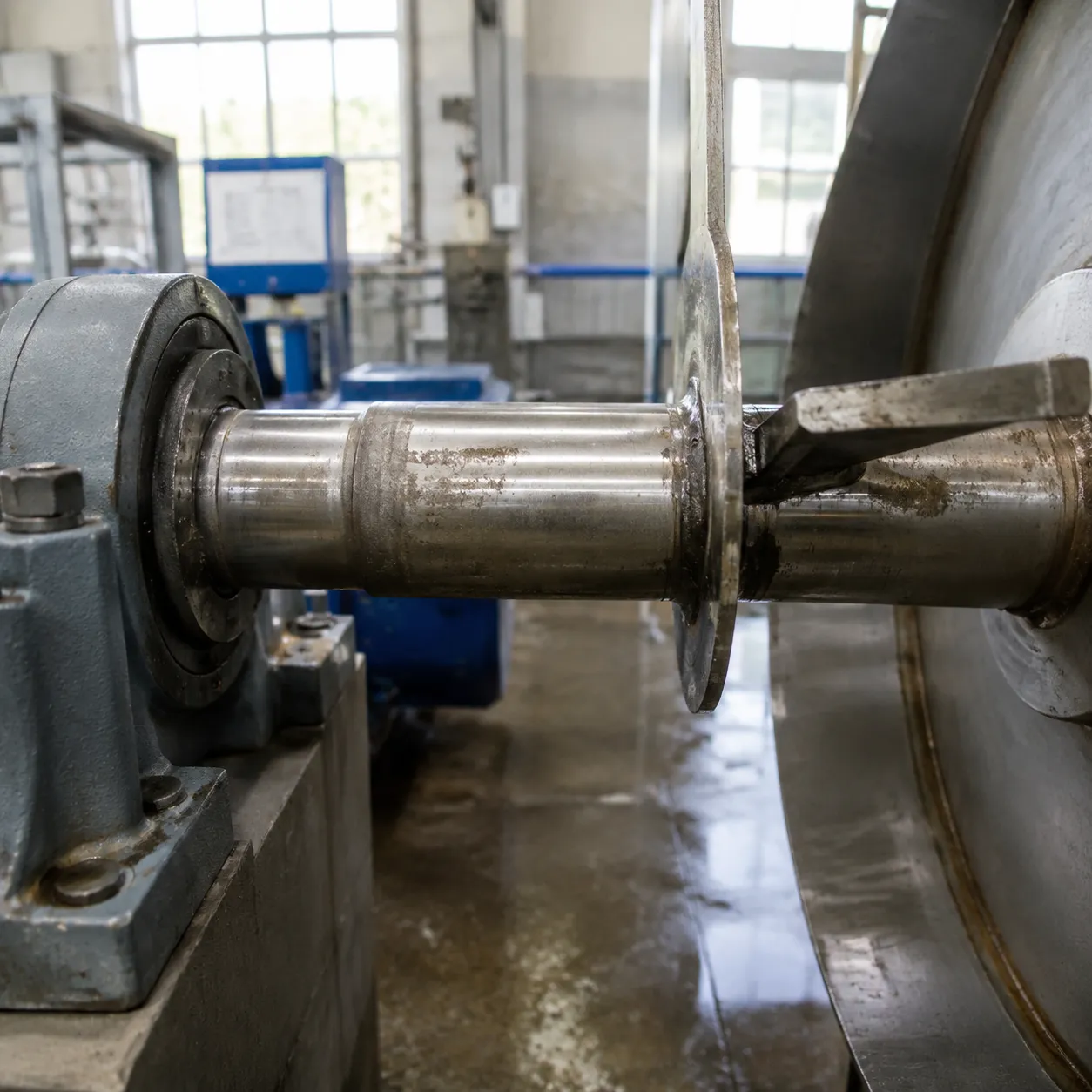
Excessive agitator shaft runout degrades mixing efficiency and causes costly mechanical failures in dairy processing systems. Identifying the root cause early prevents downtime and preserves batch quality.
Shaft Straightness and Machining Errors
Initial runout often stems directly from manufacturing or machining flaws before the equipment ever reaches the factory floor.
- Poor Concentricity: Inaccurate turning or centerless grinding creates uneven wall thickness and journal offsets along the shaft.
- Thermal Stress Release: Improper heat treatment during production causes the metal to warp as internal stresses relieve over time.
- Material Defects: Substandard raw stock with non-uniform density shifts the center of mass away from the geometric center.
For heavy-duty mixing applications, specifying high-precision custom CNC machined drive shafts ensures strict straightness tolerances right from the start.
Coupling Misalignment and Installation Conditions
Even a straight shaft experiences severe runout if installed incorrectly. Agitator shaft misalignment at the drive coupling forces the entire rotating assembly out of position.
- Angular Misalignment: Drive heads set at subtle angles flex the top of the shaft, causing circular orbital motion at the impeller end.
- Parallel Offset: Shaft centers that fail to align side-by-side apply continuous radial loads onto the upper support bearings.
- Baseplate Flexing: Thin tank tops or weak mounting flanges flex under dynamic loads, shifting the shaft centerline during operation.
Worn Bearing or Support Interfaces
Loose, worn, or corroded support structures directly amplify total indicated runout.
- Internal Bearing Clearance: Worn ball or roller tracks create excessive play, allowing the shaft to wobble out of its intended rotational path.
- Sanitary Bushing Erosion: Lower product-lubricated bushings erode over time, losing control over shaft side-play.
- Housing Tolerances: Corroded or oversized bearing bores fail to secure outer rings firmly. Using properly engineered washdown bearing housings maintains rigid alignment while withstanding harsh CIP washdown routines.
Shaft Damage and Permanent Deformation
Operational accidents and extreme processing stress can bend an otherwise sound dairy agitator shaft permanently.
- Hydraulic Shock & Sloshing: High fluid impact during sudden tank filling or high-viscosity phase shifts can bend long, slender shafts.
- Mechanical Impact: Contact with internal CIP spray balls or dropped equipment during maintenance creates localized shaft deformation.
- Thermal Bending: Rapid temperature swings between cold milk processing and high-temperature sanitization cycles induce permanent thermal bow on unconstrained shafts.
What Causes Imbalance in an Agitator Assembly?
Rotational imbalance occurs when the center of mass in a dairy agitator shaft assembly shifts away from its geometric centerline. Even minor weight offsets generate high centrifugal forces during operation, leading to severe agitator shaft vibration and premature mechanical stress.
Uneven Mass Distribution Around the Rotating Axis
When an agitator rotates, any asymmetrical mass distribution generates dynamic forces that scale exponentially with operating speed.
| Factor | Cause | Operational Impact |
|---|---|---|
| Material Inhomogeneity | Voids or density variations in raw shaft or hub stock | Constant radial pull and localized shaft flex |
| Machining Tolerances | Off-center boring of hubs, keys, or shaft couplings | Continuous offset between rotation axis and mass center |
| Asymmetrical Keyways | Unbalanced keyway slots or mismatched key stock | High-frequency rotational vibration |
Impeller, Blade and Attachment Differences
Impellers and blades are primary contributors to rotating assembly imbalance. Subtle physical differences between individual blades create uneven dynamic forces across the dairy agitator shaft.
- Blade Weight Variations: Slight thickness variations from manual grinding or inconsistent welds create heavy spots around the hub.
- Pitch Angle Mismatches: Blade angle variations cause uneven fluid resistance, adding dynamic hydraulic imbalance during operation.
- Fastener Discrepancies: Unequal bolt lengths, missing washers, or non-uniform torque application alter weight symmetry. Utilizing high-precision manufacturing, such as 5-axis CNC for food machinery components, maintains strict weight balance and tight tolerances across complex impeller geometry.
Product Buildup or Damage on Rotating Components
Operational conditions in dairy processing plants frequently disrupt agitator shaft balance over time:
- Dairy Product Buildup: Fat deposits, milk stone, and dried solids collect unequally on blade undersides, triggering abrupt vibration spikes.
- Incomplete CIP Cycles: Ineffective Clean-In-Place runs leave localized soil pockets on concealed hub corners or blade welds.
- Mechanical Blade Damage: Foreign object impacts or severe fluid shock bend blade tips, destroying both structural and hydraulic balance.
- Sanitizer Pitting: Aggressive chemical cleaners leach surface material unevenly, permanently altering component weight distribution.
How Runout and Imbalance Affect Dairy Agitator Performance
When a dairy agitator shaft suffers from excessive runout or rotational imbalance, the entire processing system pays the price. We see firsthand how subtle geometric defects quickly compound into costly operational bottlenecks and equipment downtime.
Increased Vibration During Operation
Shaft imbalance creates dynamic forces that grow exponentially with rotational speed. Combined with physical runout, this generates severe agitator shaft vibration that travels throughout the entire vessel assembly.
- Harmonic Resonance: Dynamic wobbling creates cyclic forces that shake drive mounts, top plates, and sanitary tank walls.
- Batch Disruption: Excessive vibration disrupts delicate liquid emulsification and uniform heat transfer during milk, cheese, or cream processing.
Additional Loads on Bearings and Mechanical Seals
Agitator shafts are engineered to rotate precisely along their geometric centerline. When runout pushes the center of mass outward, the resulting radial forces severely overload supporting components.
- Accelerated Bearing Wear: Heavy radial loads create localized stress points on bearing raceways, drastically shortening operating lifespan.
- Shaft Fatigue: Continuous dynamic bending causes localized stress concentration near journal shoulders and coupling connections.
Seal Interface Problems and Potential Leakage
Sanitary mechanical seals rely on continuous, parallel face contact to maintain a fluid-tight barrier. Shaft eccentricity forces seal faces to open and close thousands of times per hour.
- Sanitary Breaches: Continuous face movement creates microscopic gaps where milk solids accumulate, creating sanitation risks.
- Product Leakage: Radial displacement accelerates mechanical seal wear, resulting in product leaks—much like how proper piston seal clearance affects yogurt fill consistency across liquid dosing applications.
Reduced Mechanical Stability and Increased Component Wear
Unchecked runout degrades the mechanical integrity of the entire mixing assembly over time.
- Fastener Failure: Persistent high-frequency vibration gradually backs off drive flange bolts and mounting hardware.
- Impeller Damage: Loss of shaft rigidity subjects impeller blades to uneven fluid resistance, leading to asymmetrical wear and unbalanced shear force within the tank.
How to Check Agitator Shaft Runout
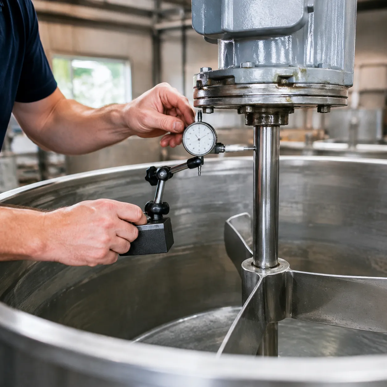
Accurate shaft runout measurement requires a controlled environment and a systematic approach. When I perform a dairy agitator shaft inspection, I stick to a proven process to capture micro-deviations before they destroy seals and bearings downstream.
Establishing the Correct Measurement Datum
Before taking readings, you must set a rigid, repeatable reference baseline.
- Mounting: Support the shaft on precision V-blocks or between lathe centers at the primary bearing journal locations.
- Stability: Anchor the setup to a heavy steel inspection table to eliminate ambient vibration.
- Datum Axis: Align the measurement plane directly with the shaft's true centerline to prevent false bending readings.
Using a Dial Indicator to Measure Runout
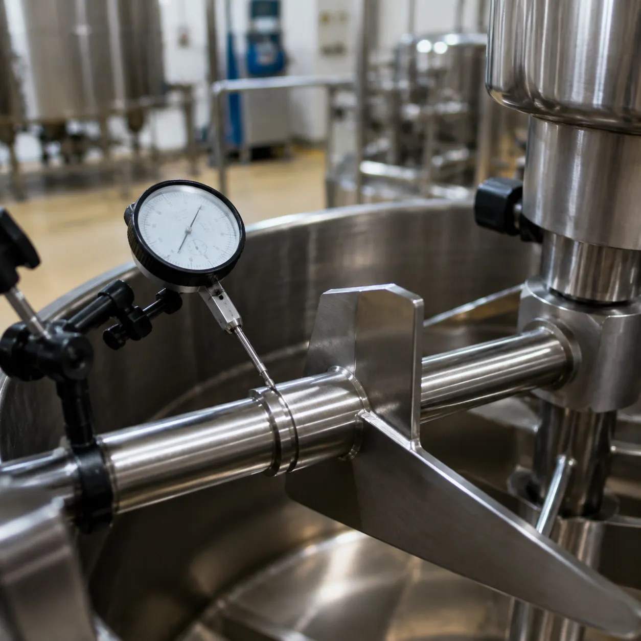
A dial test indicator (DTI) mounted on a magnetic base gives the clearest view of Total Indicated Runout (TIR).
- Positioning: Set the contact point perpendicular to the shaft surface.
- Pre-loading: Apply slight tension to the indicator stem to maintain constant surface contact.
- Rotation: Rotate the shaft by hand through a full 360-degree rotation at a slow, continuous pace.
- Recording: Note the highest and lowest needle points—the total variance equals your runout.
Checking Multiple Shaft Journals and Critical Diameters
Measuring a single spot on a long shaft will miss localized bends. I check several key zones along the entire shaft length:
- Bearing Journals: Ensures smooth load distribution and prevents premature bearing wear.
- Mechanical Seal Seats: Keeps runout minimal to protect delicate seal faces against fluid leaks.
- Coupling Fits: Guarantees proper torque transfer without introducing drivetrain wobble.
- Impeller Mount Locations: Prevents high-amplitude dynamic force at the shaft extremity.
Small inaccuracies along these points add up quickly, making it essential to manage tolerance stack-up in drive shafts during routine maintenance checks.
Comparing Results With the OEM Drawing or Specification
Once I record the TIR across all journals, I benchmark the data against the manufacturer’s technical specifications.
| Inspection Location | Typical Max Allowable TIR | Operational Risk if Exceeded |
|---|---|---|
| Bearing Journals | 0.001" – 0.002" (0.025 – 0.05 mm) | Excessive vibration and localized heat |
| Seal Interfaces | 0.001" (0.025 mm) | Batch contamination and fluid leakage |
| Impeller Seats | 0.003" – 0.005" (0.075 – 0.125 mm) | Dynamic imbalance and fatigue failure |
If your readings exceed the OEM tolerance limits, the shaft must be precision-straightened or replaced to restore equipment reliability.
What to Inspect When an Agitator Develops Excessive Vibration
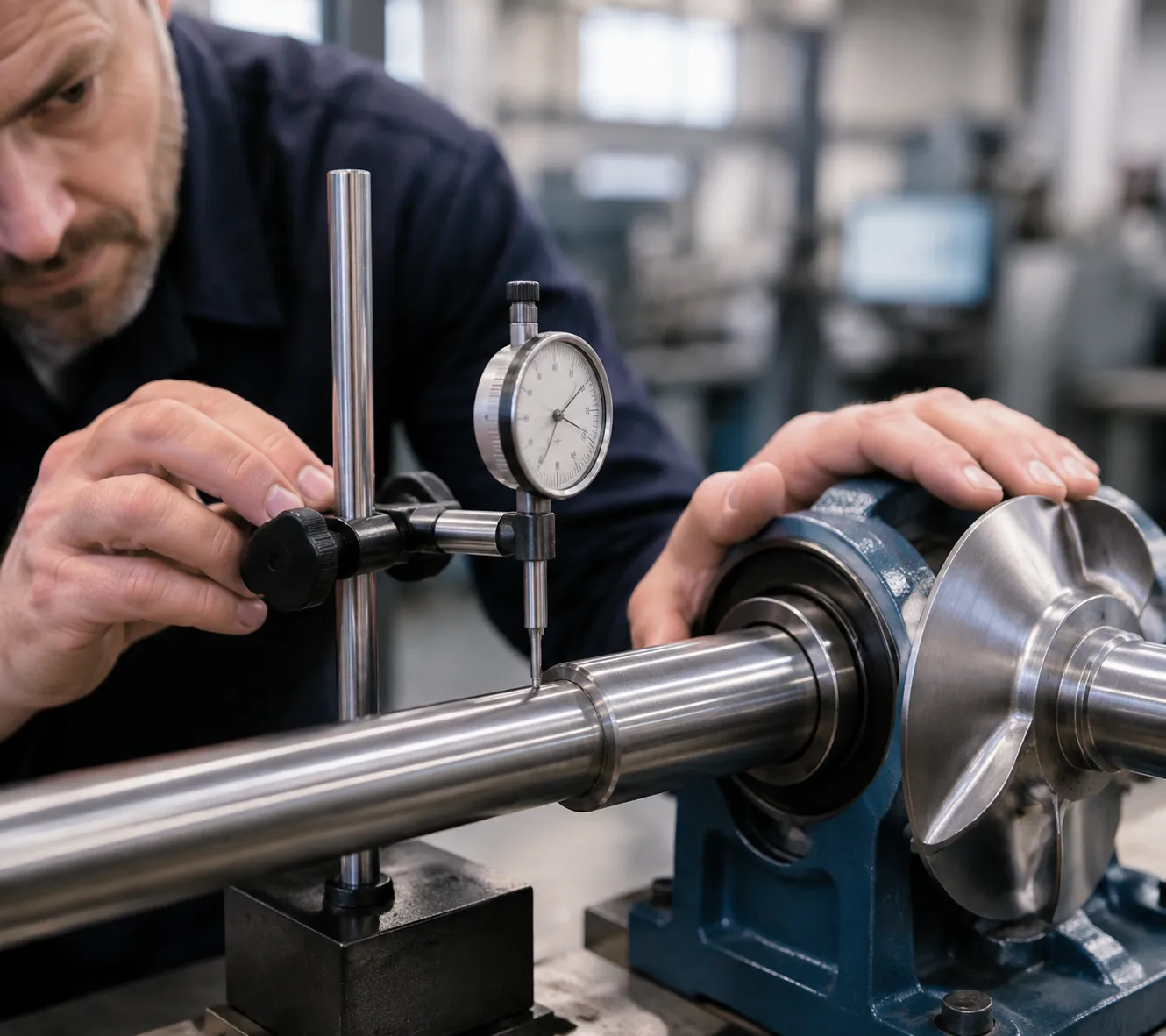
When an agitator develops sudden or escalating vibration, I perform a systematic teardown and physical inspection before replacing hardware. Isolating the mechanical source early prevents severe drive motor failure, batch contamination, and costly downtime.
Shaft Straightness and Runout
- Dial Indicator Test: Mount a dial indicator on a rigid baseline magnetic base along the shaft length and rotate it manually.
- Runout Limits: Check total indicated runout (TIR) at multiple points. Exceeding OEM tolerance specs confirms permanent shaft bending or distortion.
- Impact: Bent shafts generate relentless cyclic oscillation that accelerates agitator bearing wear and destroys seal faces.
Bearing and Seal Journal Condition
- Surface Inspection: Examine critical shaft journal areas for fretting corrosion, deep scoring, or pitting.
- Fit Integrity: Measure journal outside diameters with micrometer calipers to confirm tight fit tolerances with bearing inner rings and seal sleeves.
- Impact: Journal wear creates mechanical slop, increasing overall agitator shaft runout and directly inducing mechanical seal wear.
Coupling Alignment
- Alignment Checks: Measure parallel (offset) and angular misalignment between the drive gearbox output shaft and the agitator shaft.
- Fastener Torque: Inspect flexible coupling inserts for wear, cracking, or loose hardware.
- Impact: Coupling misalignment exerts continuous bending forces on the shaft, driving up vibration frequencies at 1X and 2X rotational speed.
Impeller and Rotating Assembly Condition
- Blade Integrity: Inspect impeller blades for mechanical impact damage, bending, or asymmetrical pitch angles.
- Product Accumulation: Clean off dried dairy solids or product buildup trapped on blade surfaces or mounting hubs.
- Impact: Uneven mass distribution or damaged blades create severe operational imbalance, spiking agitator shaft vibration during liquid processing.
When Further System-Level Vibration Analysis Is Needed
- FFT Spectral Analysis: Mount tri-axial accelerometers on drive mounts and bearing housings to gather Fast Fourier Transform (FFT) spectrum data.
- Frequency Identification: Distinguish between primary running speed peaks (1X imbalance), alignment harmonics (2X), or gear mesh frequencies.
- Structural Resonance: Run dynamic coast-down testing to verify whether normal operating speeds are exciting natural resonant frequencies of the tank structure or mounting bridge.
- When a Replacement Agitator Shaft May Be Needed
While routine maintenance solves minor alignment issues, certain physical defects demand a complete agitator shaft replacement to protect your process equipment and maintain sanitary standards.
- Permanent Shaft Deformation
Extreme dynamic loads, batch overloads, or mechanical impacts can permanently bend a dairy agitator shaft. Once a shaft suffers plastic deformation beyond allowable Total Indicator Reading (TIR) limits, machine straightening is often a temporary fix. Straightening introduces residual thermal and mechanical stresses that cause the shaft to bow again under operating temperatures and load cycles, leading to persistent agitator shaft runout and severe operational vibration.
- Worn Bearing or Seal Journals
Continuous operation eventually wears down critical shaft journals where mechanical seals and bearings sit. Excessive agitator bearing wear and grooving at the sealing surface compromise sanitary barrier fluid containment, inviting batch contamination and fluid leaks. When journal diameters drop below OEM tolerances, replacing the shaft and pairing it with high-integrity custom 316L washdown bearing housings restores precise rotational stability and prevents premature mechanical seal wear.
- Damaged Keyways, Threads or Coupling Interfaces
Fretting corrosion, shock loads, and repeated thermal cycling degrade drive connection points over time.
- Distorted Keyways: Create slop in torque transmission, increasing rotational play and accelerating dynamic imbalance.
- Stripped Threads & Damaged Flanges: Prevent proper clamping force at rigid couplings, causing localized shaft deflection during agitation.
Galling on Fit Diameters: Prevents precise concentric alignment with the drive motor or gearbox.
Manufacturing a Replacement Shaft From an OEM Drawing or Sample
We manufacture custom replacement shafts engineered to match or exceed original factory specifications. By utilizing high-grade 316L stainless steel, precision CNC turning, and rigorous dynamic balancing, we ensure your new dairy agitator shaft delivers zero-runout performance, full CIP compatibility, and long-term reliability for your processing line.