Why Spray Pattern Matters in CIP Tank Cleaning
Clean-in-place (CIP) efficiency relies entirely on delivering the cleaning fluid to every square millimeter of internal surface area. A precision-engineered CIP spray pattern ensures consistent soil breakdown, reduces wash times, and minimizes chemical usage across hygienic processing environments.
What CIP Spray Coverage Actually Means
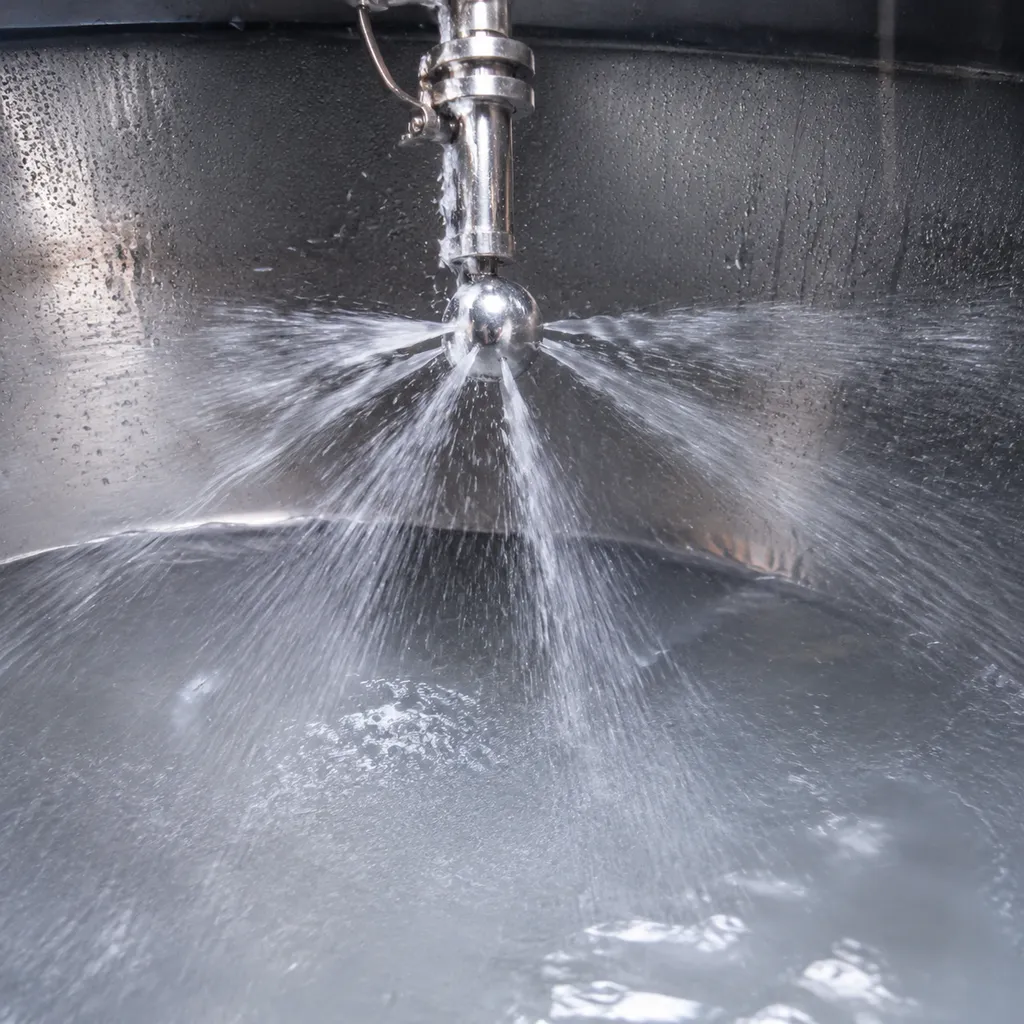
True CIP spray coverage extends beyond simply wetting the inside of a vessel. Effective coverage requires a balance of mechanical impact force, dynamic wall shearing, and liquid film cascading.
- Direct Impact Force: High-velocity fluid streams striking target surfaces to dislodge heavy soil deposits.
- Fluid Cascading: A continuous, downward-flowing film that washes non-impact zones via liquid shear.
- 100% Surface Wetting: Complete surface contact with zero dry spots, ensuring reliable microbial control.
Spray Direction vs. Effective Cleaning Coverage
A liquid stream traveling toward a vessel surface does not automatically guarantee total soil removal. Differentiating between directional liquid delivery and functional surface coverage is critical for optimizing CIP spray ball coverage:
| Feature | Spray Direction | Effective Cleaning Coverage |
|---|---|---|
| Primary Function | Linear trajectory along a calculated axis | Uniform fluid film formation and mechanical soil shear |
| Target Area | Line-of-sight impact point | Full surface wash, including runoff paths and lower sidewalls |
| Cleaning Impact | High localized force | Total vessel cleaning and hygienic validation |
Why Tank Geometry Can Create Shadowed Areas
Vessel interiors are rarely completely open. Internal obstructions create line-of-sight barriers that block direct spray streams, making tank geometry CIP coverage a critical design factor.
- Agitator Shafts & Blades: Block top-down spray vectors, creating target shadows on the underside of impellers.
- Baffles & Wall Brackets: Interrupt horizontal fluid paths, leaving hidden pockets behind structural supports.
- Instrument Dip Tubes & Ports: Deflect incoming fluid streams, requiring customized tank cleaning spray pattern coverage to clear blind spots.
How Orifice Layout Controls Spray Distribution
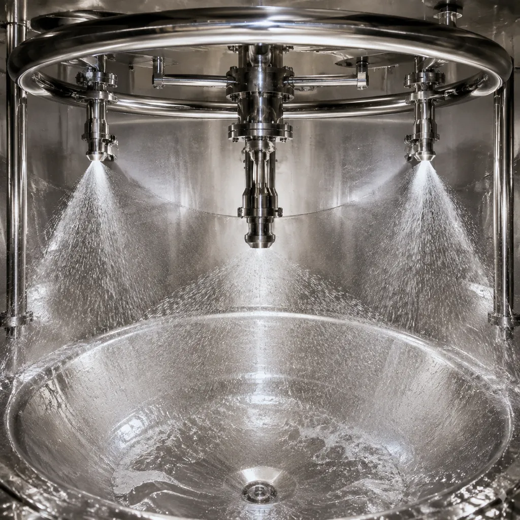
We design the CIP orifice layout to dictate exactly where cleaning fluid travels inside the vessel. The spatial arrangement of holes on a spray ball controls the fluid impact velocity, spray direction, and overall distribution pattern across tank walls.
Orifice Position and Spray Direction
- Top Dome Targeting: Upward-drilled orifices deliver direct fluid impact to the tank ceiling and top inlet ports.
- Side Wall Coverage: Horizontally aligned holes project overlapping spray bands across the vertical tank walls.
- Bottom Cone Sweeping: Downward-oriented holes flush the bottom cone, agitator seals, and vessel outlet.
The position of each CIP spray ball orifice determines whether a surface receives direct jet impact or relies on cascading falling-film coverage.
How Hole Angle Changes the Targeted Surface Area
- Focused Jet Impact: Directing holes at precise angles focuses energy on high-fouling zones, maximizing mechanical cleaning action.
- Surface Spread Control: Adjusting the spray hole angle broadens contact coverage, allowing fewer orifices to clean larger surface areas without sacrificing impact force.
- Precision Trajectory: Just as precise fluid distribution is critical in brine needle hole patterns, calculated drill angles ensure liquid streams hit specific target zones without deflecting prematurely.
Why Uneven Hole Distribution Can Create Coverage Gaps
- Shadowed Dry Spots: Misaligned or improperly spaced holes create gaps in the spray ball hole pattern, leaving uncleaned shadow zones on vessel walls.
- Pressure Drops: Clustering holes too closely starves adjacent orifices, weakening total jet impact force.
- Increased Wash Cycles: Inconsistent CIP spray coverage forces longer run times and higher chemical usage to clean stubborn spots that a balanced design would wash immediately.
How Orifice Size Affects CIP Spray Performance
Many processors assume that bigger holes mean better cleaning, but in sanitary tank cleaning, precision always trumps size. The diameter of each spray ball orifice dictates how fluid dynamics translate into physical cleaning impact on vessel walls.
Relationship Between Orifice Diameter, Flow and Pressure
Fluid velocity and system pressure work in direct tandem with hole size. When wash fluid forces through a specific orifice diameter, the resulting pressure drop creates the velocity needed to hit tank surfaces with mechanical force.
- Smaller Orifices: Increase spray velocity and throw distance at lower flow rates, but demand higher operating pressure.
- Larger Orifices: Pass a higher fluid volume, but rapidly drain line pressure if pump capacity falls short.
Maintaining steady hydraulic conditions—often supported by sanitary flow control like 316L valve manifolds for beverage lines—ensures your spray devices receive the consistent supply pressure required for full mechanical impact.
Why Larger Holes Do Not Automatically Improve Cleaning
Drilling out orifices or selecting oversized holes usually backfires. When the total orifice surface area exceeds pump delivery capacity:
- Pressure Loss: System pressure plummets across the entire spray device.
- Weak Impact: High-velocity jets degrade into low-energy streams that fail to shear stubborn soils.
- Resource Waste: Water and chemical consumption increase significantly without improving wash efficiency.
Why Orifice Size Must Match the Specified CIP Conditions
Every spray ball hole pattern must be engineered around your available supply pressure, volumetric flow rate, and wash liquid viscosity. Matching the spray ball orifice size directly to your operational parameters guarantees complete CIP spray ball coverage while maintaining optimal fluid velocity and impact energy.
How Tank Geometry Affects Spray Coverage
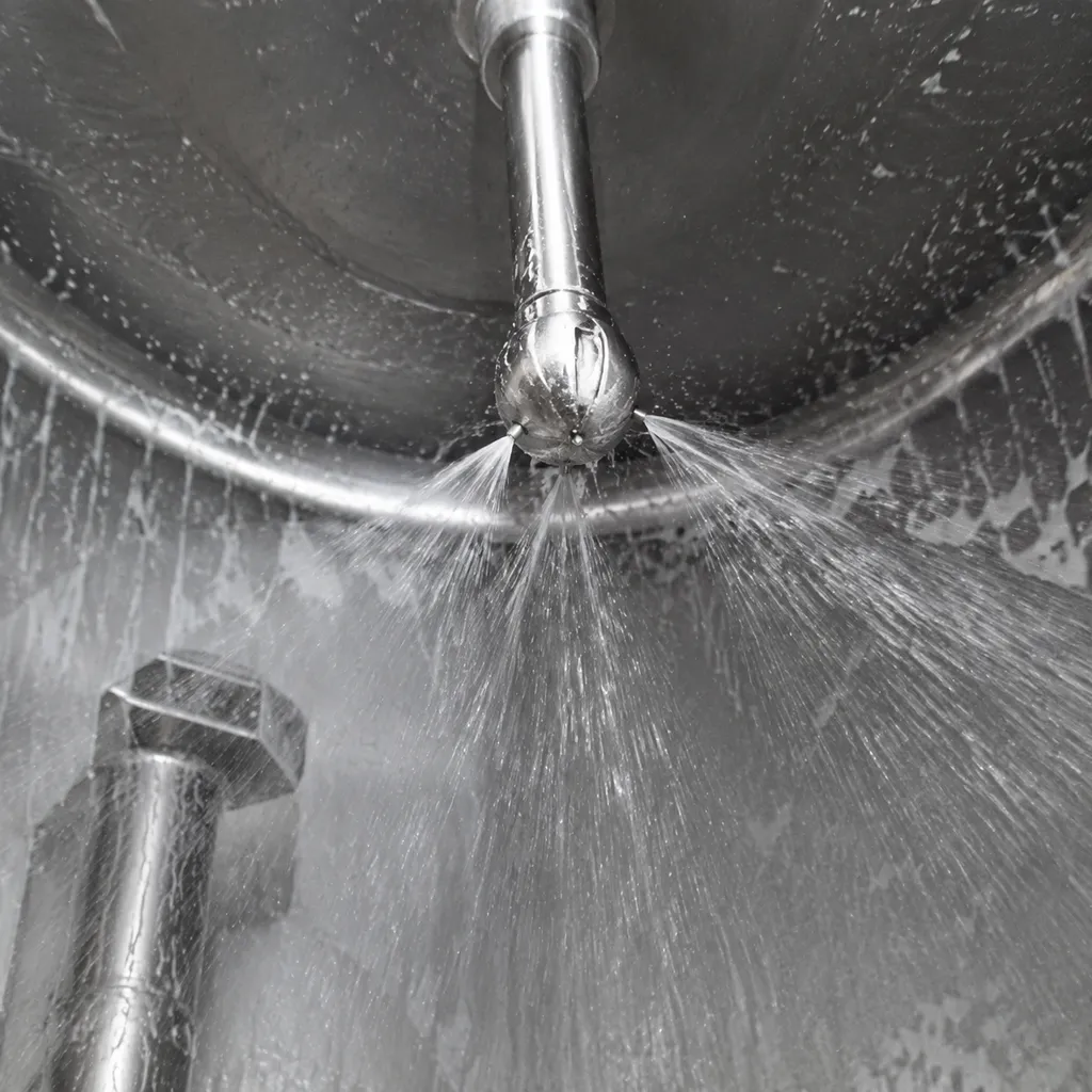
Every vessel presents unique physical hurdles. Even the most precise CIP spray ball design fails if it does not account for the specific vessel interior. Tank shape, size, and internal fixtures dictate how cleaning fluid impacts surfaces and flows down vessel walls, making tank geometry CIP coverage a critical engineering factor.
Tank Diameter, Height and Spray Ball Position
Vessel proportions determine the required throw distance and fluid impact force. As tank diameter increases, fluid velocity drops before reaching the outer shell, reducing mechanical shear stress.
| Tank Parameter | Impact on CIP Coverage | Target Strategy |
|---|---|---|
| Large Vessel Diameter | Fluid velocity drops over long distances, weakening wall impact. | Optimize spray hole angle and select larger CIP spray ball orifice sizes. |
| Excessive Vessel Height | Falling liquid film thins out before reaching the bottom dish or cone. | Implement multi-ball setups or adjust vertical positioning. |
| Shallow Top Domes | Standard streams miss upper shoulder corners. | Refine the spray ball hole pattern to direct precise fluid force upward. |
Agitators, Baffles, Ports and Other Shadowing Features
Internal obstructions block direct fluid streams, creating "shadowed" zones where standard CIP spray coverage cannot reach. Liquid hitting an agitator shaft stops abruptly, leaving the far side completely unwashed.
- Agitators and Impellers: Block horizontal spray line-of-sight, requiring targeted spray angles or dual ball arrangements.
- Baffles and Dip Tubes: Deflect cascading wall fluid, requiring dedicated directional spray ball orifice alignment behind the structure.
- Nozzles and Manways: Create dead corners on top flanges where falling fluid sheets cannot penetrate naturally.
When integrating spray hardware around complex vessel interiors, using reliable hardware like custom anodized mounts and brackets for OEM packaging and processing equipment keeps supply lines and spray heads locked rigidly in position during high-pressure wash cycles.
Why Installation Position Matters as Much as Hole Pattern
A precise tank cleaning spray pattern cannot compensate for poor physical placement inside the tank. Even a slight alignment error alters liquid trajectory and disrupts full CIP spray ball coverage.
- Vertical Height: Mounting too high starves upper vessel shoulders, while mounting too low reduces impact velocity on upper sidewalls.
- Centering: Off-center installation creates asymmetrical spray distribution, heavily washing one side while leaving the opposite wall under-cleaned.
- Pitch and Angularity: A slight tilt shifts the spray hole angle, directing liquid away from target surfaces and causing severe coverage gaps.
Manufacturing Accuracy of Spray Ball Orifices
Precision in manufacturing directly dictates CIP spray coverage. When we produce custom spray balls, even micro-level deviations in orifice geometry can jeopardize an entire cleaning cycle.
Controlling Orifice Diameter and Hole Position
Drilling standard spray ball holes requires strict CNC tolerance control. A variation of just a fraction of a millimeter in spray ball orifice size alters the liquid flow rate and pressure balance across the head. Accurate spray ball hole pattern positioning ensures fluid hits every intended square inch of the tank interior uniformly. To keep spray distribution predictable, understanding how to manage tolerance stack-up across multi-axis drilling processes is essential.
Maintaining the Specified Spray Hole Angle
The spray hole angle determines the trajectory and reach of the cleaning fluid.
- Direct Impact: Misaligned angles cause liquid jets to miss target surfaces, creating dead zones above or below internal tank fixtures.
- Machining Precision: We maintain precise multi-angle indexing during machining so every jet targets its assigned zone without overlapping inefficiently or leaving gaps.
Why Burrs and Partially Blocked Orifices Matter
Internal micro-burrs created during drilling disrupt fluid dynamics, turning a solid jet into an unpredictable spray mist. Burrs also catch product debris and accelerate chemical buildup, quickly choking off fluid delivery. Ensuring clean post-machining finishes—similar to when stainless components need electropolishing—is non-negotiable for maintaining smooth internal fluid paths and sanitary operation.
Inspecting Small Holes and Orifice Patterns
Visual checks alone cannot guarantee CIP orifice layout accuracy. We use dedicated inspection tools and flow testing to verify every head before deployment:
- Pin Gauge Verification: Checks uniform diameter across every drilled hole.
- Optical Pattern Mapping: Verifies correct multi-axis hole placement and jet angles.
- Hydrostatic Flow Testing: Confirms proper pressure drops and validates expected tank cleaning spray pattern consistency.
Why CIP Spray Patterns Change Over Time
Even the best CIP spray ball design will not maintain factory-level performance forever. Operating harsh washdown cycles, continuous pressure shifts, and aggressive chemical exposure gradually alter your CIP spray pattern, leading to missed spots and compromised tank hygiene.
Product Residue and Orifice Blockage
- Debris Trapping: Heavy product residues, fibers, or particulates can settle inside the spray ball orifice, causing partial or total blockages.
- Pattern Distortion: Blocked holes redirect fluid flow unexpectedly, distorting the intended spray hole angle and creating severe shadow zones across your tank walls.
- Coverage Loss: Reduced fluid discharge directly shrinks your effective CIP spray coverage, leaving uncleaned surfaces behind.
Mineral Deposits and Cleaning Chemical Buildup
- Scale Accumulation: Hard water minerals and chemical precipitates coat the interior and exterior of each hole, restricting the spray ball orifice size.
- Velocity Shifts: Constricted openings alter system pressure and fluid velocity, disrupting the uniform tank cleaning spray pattern.
- Dampened Impact: Scale buildup dampens the mechanical impact force needed to break down tough soil, forcing longer cleaning cycles.
Orifice Damage, Wear and Deformation
- Erosion & Corrosion: High-velocity CIP fluid paired with chemical exposure steadily erodes hole margins over time.
- Pattern Misalignment: Physical wear or handling damage distorts the engineered spray ball hole pattern, shifting fluid away from critical high-soil target areas.
- Pressure Drop: Enlarged or deformed orifices drop system backpressure, drastically reducing overall CIP spray ball coverage. Replacing degraded components with precision-machined wear parts restores proper spray geometry and keeps your cleaning process efficient.
What to Check When CIP Coverage Becomes Inconsistent
When CIP spray coverage fails to clean tank surfaces evenly, systematic troubleshooting prevents batch contamination and unnecessary downtime.
Compare the Actual Orifice Pattern With the Original Specification
Verify that the spray ball hole pattern matches the original vessel design parameters. Unapproved modifications or generic replacements often feature an altered CIP orifice layout that disrupts intended fluid trajectories and leaves upper tank zones unwashed.
Inspect Hole Condition, Orientation and Blockage
Examine each CIP spray ball orifice for debris, chemical scaling, or mechanical wear. Even minor distortion to the spray hole angle alters fluid distribution across the vessel wall. Implementing strict quality inspection routines helps identify microscopic orifice damage, burrs, or partial clogs before they cause full cleaning failures.
Check Spray Ball Position and Tank Obstructions
Physical shifts inside the vessel immediately create shadowed blind spots:
- Vertical Alignment: Ensure the spray ball has not slipped, tilted, or shifted off-center from its mounting pipe.
- Internal Obstructions: Inspect for newly added agitator blades, dip tubes, or sensors blocking the direct spray line.
- Targeted Orientation: Confirm high-impact spray paths aim directly at critical areas like tank top-heads and inlet ports.
Confirm System Flow and Pressure Conditions
Even a perfectly manufactured CIP spray ball design fails if supply parameters fall out of specification:
- Insufficient Pressure: Causes fluid streams to drop early, reducing throw distance and impact force.
- Excessive Pressure: Generates atomization and misting, destroying the solid streams required for effective mechanical wall breakdown.
- Flow Rate Fluctuation: Leaves lower tank sections starved during timed wash cycles.
When a Custom Replacement CIP Spray Ball Is Needed
When standard spray balls fail to deliver complete coverage, our are engineered to your exact orifice layout and spray hole anglestandard off-the-shelf units rarely deliver complete CIP spray coverage. Standard components often fail to match specific tank geometries or modified flow rates. In these cases, a custom replacement engineered to your exact CIP orifice layout and spray hole angle is required to maintain reliable clean-in-place efficiency.
Damaged or Enlarged Spray Orifices
Over time, aggressive cleaning chemicals, thermal cycling, and abrasive residues wear down internal spray surfaces.
- Impact of Orifice Wear: As the spray ball orifice size expands beyond original tolerances, system pressure drops and fluid velocity falls off dramatically.
- Loss of Impact: Larger, worn holes ruin the intended tank cleaning spray pattern, turning targeted jets into weak, inefficient streams.
- Coverage Shadowing: Physical erosion skews the discharge trajectory, creating severe coverage gaps inside the vessel.
Obsolete OEM Spray Ball Designs
Operating legacy process vessels often means dealing with discontinued or hard-to-find components. When an original OEM unit fails, sourcing an exact match off the shelf is rarely an option.
- Outdated Hole Patterns: Older vessels frequently feature unique mounting connections and custom spray ball hole patterns designed for non-standard tank shapes.
- Process Upgrades: Changing pump capacities or chemical delivery rates means an outdated CIP spray ball design can no longer deliver adequate impact.
- Risk of Incomplete Cleaning: Substituting an obsolete unit with a generic ball leads to poor tank geometry CIP coverage and potential batch contamination.
Manufacturing a Replacement From a Drawing or Defined Specification
We build precise replacement units manufactured directly from engineering drawings, physical samples, or target performance specifications.
- Tailored Hole Angles: We precision-drill each CIP spray ball orifice to directly hit internal agitators, baffles, ports, and vessel heads.
- Exact Flow Matching: Hole counts and sizes are engineered to optimize your current flow rates and operating pressure.
- Precision CNC Machining: We utilize advanced custom CNC food-grade stainless steel manufacturing techniques to guarantee smooth, burr-free orifices and tight dimensional accuracy.
Related Sources
- https://www.spray.com/products/tank-cleaning/tankjet-63225-and-63225-3a
- https://www.alfalaval.com/globalassets/documents/industries/sanitary-general/thinking-ahead/new-pdfs/ese02286en-01-tank-optimization-controlling-hygienic-tank-cleaning.pdf
- https://www.gea.com/en/products/cleaners-sterilizers/tank-cleaning/static-cleaners/spray-balls-tank-
- https://www.spray.com/products/tank-cleaning/tankjet-63225-and-63225-
- https://www.alfalaval