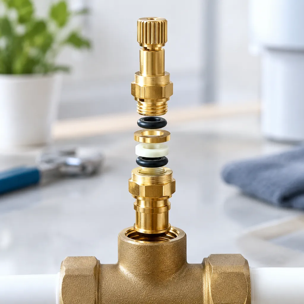
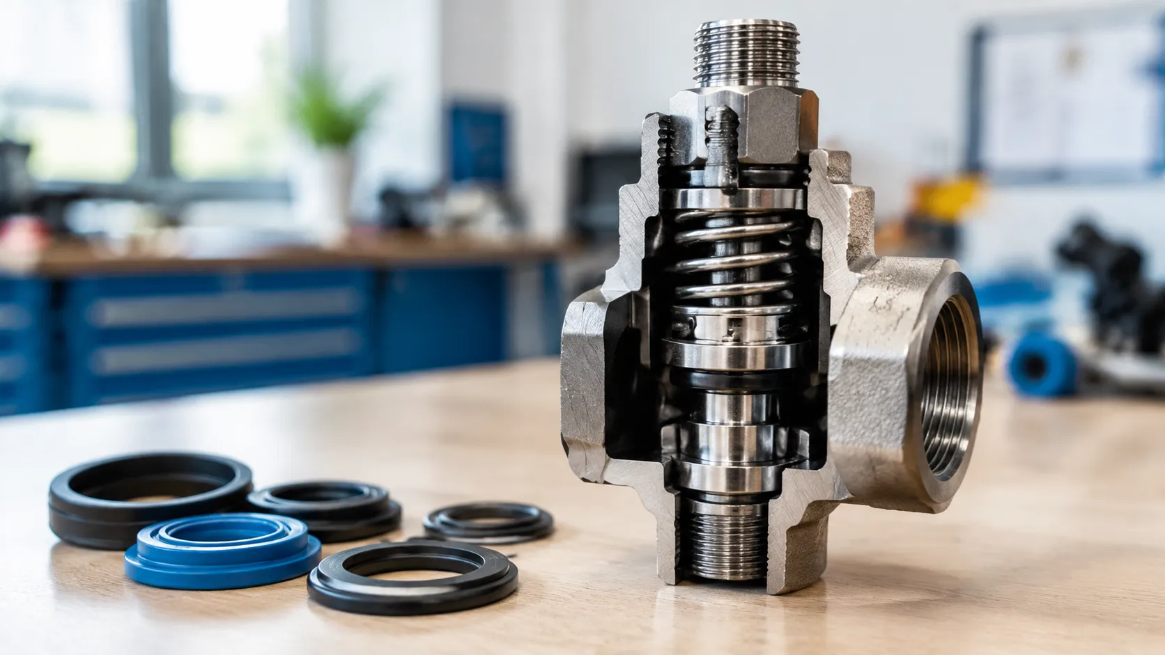
Are you struggling with persistent foaming, pressure leaks, or inconsistent fill levels on your packaging line? The root cause often comes down to a critical detail many operators overlook: valve and seal geometry.
In beverage bottling and canning, mastering counter-pressure filling (also known as isobaric filling) demands. Valve-seat geometry, stem alignment, vent-tube design, and seal-groove dimensions can materially influence pressure stability, foaming behavior, seal wear, and filling consistency in counter-pressure systems.
Whether you want to eliminate pressure loss, prevent premature seal wear during CIP cycles, or manufacture ultra-precise replacement components, understanding how fluid dynamics intersect with mechanical design changes everything.
In this guide, you'll learn exactly how valve and seal geometry affects counter-pressure filling performance and how to keep your line running at peak efficiency. Let's dive right in!
Understanding Valve and Seal Geometry in Counter-Pressure Filling
Precision counter-pressure filling relies on exact mechanical tolerances to maintain carbonation, prevent foaming, and ensure product stability. Understanding how valve components and seal profiles interact under isobaric conditions is essential for optimizing beverage packaging lines.
What Is Counter-Pressure (Isobaric) Filling?
Counter-pressure (isobaric) filling is a technique used for carbonated liquids where the receiving container is pressurized with inert gas (CO_2or N_2) to equal the pressure of the filler bowl before liquid enters. Equalized pressure prevents dissolved carbon dioxide from escaping during the fill cycle.
- Pre-Pressurization: Gas fills the sealed container until internal pressure matches the storage bowl.
- Laminar Product Transfer: Gravity feeds the liquid into the container under equalized pressure, suppressing turbulence.
- Gas Venting: Displaced gas exits smoothly through a vent tube as liquid fills the container.
- Snifting: Controlled pressure release vent reduces internal bottle pressure to atmospheric levels without triggering foam breakout.
How Filling Valves Control Gas, Product, and Pressure
Counter-pressure filling valves act as multi-stage fluid control centers. They direct gas, isolate product channels, and modulate venting sequences in rapid, automated cycles.
| Valve Function | Operational Role | Key Geometry Focus |
|---|---|---|
| Gas Equalization | Charges container with $CO_2$ prior to liquid release | Vent tube diameter and internal porting |
| Product Dispensing | Channels carbonated beverage smoothly down container walls | Stem angle, seat profile, and flow passages |
| Hermetic Sealing | Isolates internal filling pressures from atmospheric leaks | O-ring groove dimensions and seat contact area |
| Snifting / Exhaust | Releases headspace pressure safely before container exit | Exhaust orifice diameter and throttling needle profiles |
Why Valve and Seal Geometry Matters in Carbonated Beverage Filling
Sub-millimeter variations in valve and seal geometry directly impact filling accuracy, product yield, and beverage quality. Imprecise component design leads to costly operational downtime and product waste.
- Foam Control: Smooth internal flow paths prevent shear stress and sudden pressure drops that trigger excessive foaming.
- Carbonation Retention: Tight sealing geometry maintains steady isobaric pressure, keeping dissolved gas fully integrated in the liquid matrix.
- Dissolved Oxygen (DO) Reduction: Engineered gas-channel geometry ensures efficient purging, minimizing oxygen pickup.
- Leak Prevention: Optimized O-ring cross-sections and groove clearances prevent pressure losses under continuous high-frequency cycling.
Critical Valve Geometry That Affects Filling Performance
Valve Seat Geometry and Sealing Contact Area
The angle, radius, and contact width of the valve seat directly determine pressure integrity under isobaric conditions.
Narrow Contact Width: Increases sealing force per unit area, providing an immediate gas-tight seal, but can lead to accelerated elastomeric wear if over-compressed.
Wide Contact Width: Distributes seating force over a larger area, extending seal life, but requires higher actuator forces to prevent micro-leaks under high counter-pressure.
Bevel Angle Optimization: A precise conical seat geometry ensures uniform circumferential compression, keeping gas sealed during pressurization.
Valve Stem Concentricity and Alignment
A valve stem operating off-center introduces uneven wear patterns and sudden pressure loss across the sealing surface.
Runout Control: Stem runout must be held within tight micrometer tolerances to prevent seal pinching and radial pressure imbalance.
Axial Alignment: Aligned actuation keeps the sealing surface completely parallel to the seat throughout the cycle, eliminating side-loading forces that compromise the dynamic sealing interface.
Flow-Passage Geometry and Product Flow Stability
Internal flow channels dictate how carbonated liquids travel into the container without turbulence or off-gassing.
Smooth Radius Transitions: Eliminating sharp internal corners prevents localized pressure drops that trigger CO2 breakout.
Optimized Internal Contours: Utilizing high-precision components, such as 5-axis CNC machined rotary valve bodies with complex geometries, maintains laminar flow velocity and protects carbonation retention.
Streamlined Valve Plungers: Tapered liquid path geometry reduces shear stress on the beverage, driving significant foaming reduction during high-speed fill cycles.
Vent Tube Geometry and Controlled Gas Release
The vent tube regulates displaced gas during filling and dictates the final liquid level inside the bottle or can.
Inner Bore Uniformity: A polished, consistent internal bore prevents liquid droplets from clinging inside the passage and disrupting return gas evacuation.
Tip Profile & Cut-Off Edge: Crisp, chamfered vent tube tips ensure immediate surface-tension shut-off, eliminating fill-level variation across high-volume filling lines.
How Seal Geometry Controls Pressure Integrity
O-Ring Cross-Section and Groove Geometry
The geometric relationship between an O-ring seal and its retaining groove determines whether a valve holds pressure during isobaric filling. Selecting the correct O-ring cross-section ensures the seal responds predictably when pressurized with CO_2 or nitrogen.
- Gland Fill Volume: O-ring gland fill, squeeze, groove width, and extrusion gap should follow the seal manufacturer’s design guidance and the OEM operating specification. ZSCNC machines these features to the approved drawing requirements.
- Groove Radius: Radius corners prevent stress concentration on the elastomer while eliminating sharp edges that slice seals during installation.
Compression, Squeeze, and Sealing Contact Pressure
Initial mechanical squeeze creates the baseline seal before system pressure takes over. When gas pressurizes the valve, it forces the O-ring against the downstream groove wall, creating a self-energized pressure barrier.
| Seal Type | Target Squeeze Range | Impact of Under-Squeeze | Impact of Over-Squeeze |
|---|---|---|---|
| Static Seals | 15% – 25% | Low-pressure gas leaks during pre-evacuation | Seal pinching, permanent deformation |
| Dynamic Seals | 10% – 18% | Carbonation loss, fill level instability | Excessive valve friction, rapid wear |
Extrusion Gap Under Filling Pressure
Under high isobaric pressure, soft elastomeric materials behave like viscous fluids, trying to flow into any available clearance gap. Controlling this extrusion gap is critical to extending seal lifespan.
- Machining Clearances: Tight tolerances on valve stems and sleeves keep clearance gaps below 0.1 mm, preventing high-pressure gas from tearing the seal.
- Pressure Limits: Higher filling pressures require narrower clearance gaps or harder elastomer durometers (75–90 Shore A) to prevent material shearing.
- Backup Rings: In high-pressure application lines, secondary support rings eliminate the risk of elastomer nibbling altogether.
Static vs. Dynamic Sealing Interfaces
Counter-pressure filling valves rely on both stationary and moving seals. Each requires distinct geometric considerations to maintain pressure integrity:
- Static Interfaces: Bottle neck seals and body joints require consistent, high contact pressure across fixed mating faces.
- Dynamic Interfaces: Valve stems, gas vent sleeves, and liquid plungers move continuously. Dynamic sealing demands an optimized surface finish for sliding components to minimize friction while holding gas tight.
Integrating custom-machined sealing modules ensures accurate alignment between moving stems and fixed seats, protecting dynamic seals from uneven wear and maintaining consistent filling cycles.
How Valve and Seal Geometry Affects Beverage Filling Quality
In isobaric filling, beverage quality hinges directly on precision engineering. When we manufacture high-performance counter pressure filling systems, we focus heavily on how valve and seal geometry dictates product stability, taste profile, and overall shelf life.
Maintaining Gas Tightness During Isobaric Pressurization
Proper seal contact geometry ensures the bottle pre-pressurization phase holds exact target pressure before liquid flows.
Zero pressure drops: Correct seal squeeze keeps the purge gas fully contained.
Oxygen control: Preventing leaks during pressurization blocks ambient air ingress, keeping dissolved oxygen levels to a minimum.
Uniform container sealing: Balanced sealing surface geometry provides a reliable seal against variable container neck finishes.
Reducing Foaming During Product Filling
Foaming during product transfer slows down line speeds and leads to fill-level inconsistency. Foaming during product transfer can slow down line speeds and contribute to fill-level inconsistency. Carefully machined liquid passages in our custom 316L filling nozzles for beverage lines can help control fluid flow and reduce unnecessary turbulence.
- Gradual valve seat tapers: Eliminate abrupt fluid directional changes that trigger micro-cavitation.
- Streamlined vent tube geometry: Prevents liquid from splashing into the gas return channel.
- Polished inner radii: Ensures smooth liquid wall-adhesion as the beverage slides down the bottle interior.
Supporting Carbonation Retention
Maintaining carbonation retention requires strict pressure balance throughout the fill cycle. Valve geometry maintains equalized counter-pressure between the bowl and the bottle, ensuring carbon dioxide remains fully dissolved in the liquid rather than flashing off into gas.
| Geometry Factor | Impact on Carbonation |
|---|---|
| Optimal Valve Seat Angle | Prevents liquid shear forces that break gas-liquid bonds. |
| Precise Vent Tube Diameter | Ensures consistent liquid displacement without pressure fluctuations. |
| Tight Seal Tolerances | pressure micro-leaks that cause $CO_2$ to break out of solution. |
Controlling Pressure Release During Snifting
The snifting stage vent geometry controls how headspace gas exhausts before bottle release. If exhaust channels are incorrectly proportioned, sudden pressure drops cause violent product gushing and severe foaming. Precise micro-channel geometry in the snift valve allows for controlled, multi-stage depressurization, keeping the liquid completely calm when the bottle unseals.
Surface Finish and Machining Accuracy at Sealing Interfaces
Machining accuracy and sealing surface finish directly dictate how well a counter pressure filling valve holds pressurization without leaking gas or beverage. Precise valve and seal geometry ensures uniform sealing contact pressure across every fill cycle.
How Surface Roughness Affects Valve Seat Sealing
Microscopic peaks and valleys on a valve seat create tiny pathways for carbon dioxide to escape during isobaric pressurization. A coarse surface finish compromises seal contact, requiring excessive mechanical closing force that rapidly degrades elastomer components.
| Surface condition | General consideration |
|---|---|
| Coarse or damaged surface | May increase leakage paths and seal wear |
| Controlled machined finish | Suitable when it meets the seal/OEM specification |
| Fine polished/electropolished finish | May improve cleanability and sealing-surface consistency where specified |
How Concentricity and Runout Affect Dynamic Seals
Dynamic sealing interfaces require exact component alignment to maintain uniform O-ring squeeze during valve actuation. When a valve stem or sleeve exhibits radial runout, the seal experiences uneven compression—leading to localized blow-by and fast seal degradation.
Just as managing shaft runout and balance performance ensures smooth operational stability in sanitary fluid systems, keeping minimal concentricity tolerances on dynamic sealing surfaces stops seal distortion, prevents product leakage, and maintains consistent pressure during counter-pressure filling.
Why Burrs and Edge Defects Can Damage O-Rings
Small machining burrs or sharp chamfer transitions instantly ruin dynamic and static seals during assembly or routine operation:
- Shear Damage: Sharp groove entry angles cut the outer profile of an O-ring seal during installation.
- Micro-Tearing: Rough burrs create stress concentration points, tearing elastomeric materials under high isobaric pressures.
- Actuation Resistance: Unpolished edge transitions increase friction, causing valve stickiness and inconsistent fill levels.
Balancing Tight Tolerances With Functional Requirements
We balance high-precision CNC machining with practical manufacturing limits to optimize component cost and sealing performance:
- Targeted Precision: Reserve ultra-tight dimensional tolerances for the valve seat geometry, stem guides, and sealing surface contact areas.
- Standardized Gland Designs: Machining O-ring grooves to exact depth and width standards ensures controlled compression (typically 15% to 25%) without over-stressing the seal.
- Thermal Allowance: Factor in material thermal expansion rates to prevent valve stem binding during hot CIP cleaning cycles.
- Valve Geometry, Hygiene, and CIP Cleanability
Avoiding Crevices and Product-Trap Areas
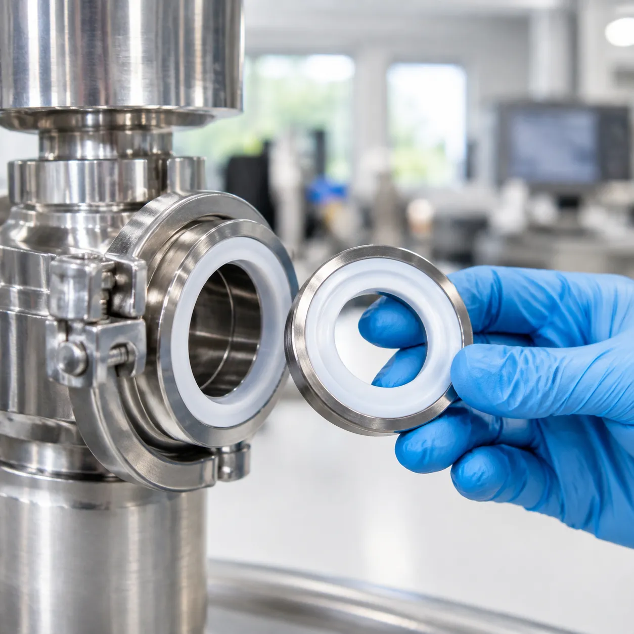
- Smooth Radii: Internal flow channels require smooth, rounded transitions rather than sharp 90-degree corners. Sharp angles create dead zones where product residue collects, and bacteria can grow.
- Flush Sealing Interfaces: O-ring grooves and valve seats must align flush with the fluid path, preventing pockets where beverage syrup or yeast can settle.
- Self-Draining Contours: Internal components are engineered with sloped surfaces so wash fluids drain completely during Clean-In-Place (CIP) cycles, leaving no standing liquid behind.
Surface Finish on Product-Contact Components
- Micro-Smooth Surfaces: Polishing product-contact surfaces to a fine finish (0.4 µm Ra or better) prevents microscopic biofilm adhesion and beverage buildup.
- Electropolished Stainless Steel: Electropolishing removes micro-peaks from machined stainless steel, making it easy for caustic and acid solutions to strip away stubborn deposits.
- Optimized Wash Coverage: Flow paths must allow cleaning fluids to sweep through all contact points evenly, which works best when paired with proper fluid delivery systems like an effective CIP spray pattern and orifice layout.
Material and Geometry Considerations for Repeated CIP Cycles
| Consideration | Design Strategy | Functional Benefit |
|---|---|---|
| Thermal Expansion | Calculate expansion gaps for hot wash cycles up to 85°C (185°F). | Prevents dynamic valve stems from binding or over-compressing elastomers. |
| Chemical Resistance | Pair food-grade EPDM, FKM, or PTFE with stress-relieved groove contours. | Avoids chemical degradation, swelling, and permanent compression set. |
| High-Velocity Wash | Reinforce seal retaining lips and apply generous edge chamfers. | Prevents high-pressure CIP fluid from dislodging or tearing elastomeric seals. |
Common Geometry-Related Problems in Counter-Pressure Filling

Pressure Leakage From Worn or Misaligned Sealing Surfaces
When valve seat geometry degrades, or alignment shifts off-center, the sealing interface loses uniform contact. We frequently see this cause gas leaks during pressurization, dropping container pressure before liquid injection.
Root cause: Uneven sealing surface contact or worn valve seats.
Operation impact: Loss of isobaric balance, leading to product breakdown and pressure loss.
Solution: Upgrading to Precision-machined replacement components can help restore the specified mating geometry and sealing interfaces when the original parts are worn or damaged.
Excessive Foaming From Unstable Flow or Pressure Release
Distorted valve stem geometry or rough inner flow passages create fluid turbulence during beverage transfer.
Turbulent flow paths: Unintended geometry changes agitate carbonated liquids during fill cycles.
Uncontrolled snifting: Wear on vent tube tips and exhaust channels creates abrupt pressure drops, causing CO2 breakout and heavy foam.
Premature O-Ring Wear From Poor Groove or Edge Geometry
Incorrect O-ring groove dimensions and sharp machining edges drastically shorten seal lifespan.
Improper compression: Incorrect squeeze ratios lead to rapid dynamic seal degradation.
Extrusion failure: Oversized extrusion gaps let seals pinch and tear under system pressure.
Sharp edges: Unchamfered groove corners slice elastomeric seals during installation and continuous valve movement.
Fill-Level Variation Caused by Valve Component Wear
Dimensional wear on vent tubes, stems, and valve sleeves disrupts precise liquid cutoff points.
Vent tube erosion: Subtle geometry changes at the vent tip shift the actual shutoff volume.
Stem friction: Drag on dynamic sealing surfaces delays valve actuation timing.
Package inconsistency: Produces fill-height variations across filling heads on the line.