
For a repeat nozzle order, define the connection standard, sealing method, mating geometry, inspection criteria and drawing revision before machining begins. An outside diameter or a photograph alone does not describe a complete filling nozzle interface.
This guide helps packaging equipment buyers prepare filling nozzle connection specifications for custom machined components. It covers the information needed for quotation, sample review and repeat batch supply. Filling accuracy, shut-off behavior and cleaning performance also require validation on the assembled machine.
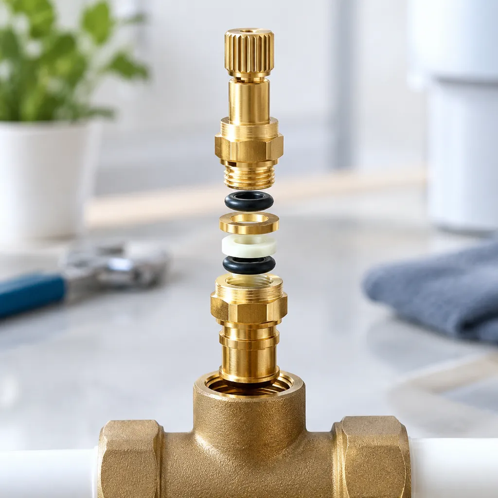
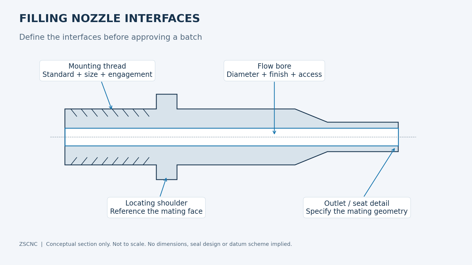
Image note: the featured filling scene is illustrative. The diagram below is a conceptual explanation, not a production drawing or evidence of an inspected customer assembly.
Define the Component and Assembly Scope
Start by identifying exactly what the supplier will deliver: a nozzle tip, body, connecting sleeve, valve stem, seat insert or an agreed set of machined parts. An individual component quotation does not automatically include seals, actuators, assembly or a tested filling head.
Identify What Is Included
- Part identification: provide a part number, approved drawing revision and quantity for each item.
- Mating parts: identify the manifold, stem, gasket, clamp or mounting bracket that controls the fit. Provide the relevant interface dimensions when available.
- Assembly scope: state whether components are supplied separately or require an agreed assembly process. List purchased seals and other bought-in items separately.
- Material documents: specify the material grade and requested traceability or certificate type at the RFQ stage. Document availability and scope must be confirmed with the order.
ZSCNC reviews custom nozzle components for CNC turning and milling to approved drawings. Our normal dimensional capability is around ±0.01 mm; selected features may be considered at ±0.005 mm after reviewing material, geometry, process and measurement access. These figures are not blanket thread, runout or assembly specifications.
Specify Connection Standards and Sealing Methods
Write the complete connection callout rather than simply “BSP,” “metric” or “sanitary connection.” Similar-looking connections can have different thread forms, sizes, engagement requirements and sealing arrangements.
| Interface | Include in the drawing or RFQ | Sealing detail to confirm |
|---|---|---|
| Parallel thread | Standard, nominal size, pitch, tolerance class where applicable, usable depth and lead-in | Identify the separate sealing face, washer, gasket or O-ring arrangement |
| Tapered pipe thread | Exact standard and size, engagement or gauging requirements, mating connection | Confirm permitted sealant and assembly requirements with the equipment designer |
| Clamp / ferrule | Applicable standard, ferrule dimensions and mating clamp and gasket details | Define the gasket contact faces; “Tri-Clamp” alone is insufficient dimensional information |
| Custom flange | Hole pattern, locating pilot or dowels, mounting face and orientation | Provide the face-seal or groove geometry and the approved seal specification |
Thread engagement and fluid sealing are different requirements. The OEM should confirm the selected connection and seal for the fluid, pressure, temperature and cleaning conditions. A component manufacturer should not infer compatibility from the material name alone.
Protect the Seal During Assembly
Identify burr-sensitive edges, lead-in chamfers, thread runouts and surfaces crossed by a seal during installation. Specify edge conditions on the drawing. Thread acceptance should follow the applicable standard and agreed gauging method, rather than a universal ±0.005 mm statement.
Define Sealing Seats and Alignment Datums
A filling nozzle sealing seat must be described together with its mating component. Provide the seat profile, contact diameter, angle or radius where relevant, and the relationship to the locating features used in assembly.
- Conical or shaped seats: define the actual profile and its geometric relationship to the guide bore or other functional reference. Do not assume a universal seat angle.
- Seal grooves: identify the approved seal and specify groove width, depth, corner radii, clearance and edge conditions as applicable.
- Flat faces: identify the contact area and drawing requirements for flatness, orientation or runout where functionally needed.
- Datum references: select them from how the nozzle is located in the machine. A mounting shoulder or bore may be relevant, but datum letters and the inspection setup are drawing-specific.
Where a seat and stem are supplied together, agree whether they are interchangeable across the batch or maintained as identified matched sets. For stem-specific quotation details, see the filling valve stem specifications RFQ checklist.
Agree Surface Finish and Inspection Requirements
Assign surface finish requirements to the relevant product-contact, sealing and sliding areas. One Ra value should not be applied automatically to every surface. Seal type, motion, machining access and the equipment's cleaning requirements influence the drawing specification.
Include the required roughness parameter and limit, measurement locations and any special measurement conditions. For hard-to-access internal passages or small seats, confirm how the requirement can be verified before accepting the order. See also our surface finish guide for sealing and sliding components.
Set the Batch Acceptance Plan Before Production
- Mark critical characteristics and agree the measurement method for threads, bores, seat geometry and functional relationships.
- Confirm sample approval requirements, inspection frequency and the records needed for each batch.
- Specify whether dimensions and finish are accepted before or after any agreed finishing operation.
- Request material documentation and inspection reports explicitly; confirm their scope, availability and any additional cost with the quotation.
- Agree protective packing for exposed threads, seats and finished surfaces.
A dimensional or roughness check does not by itself prove that an assembled nozzle will be leak-free. Static leak or pressure testing is a separate activity: the assembly scope, equipment, medium, pressure, duration and acceptance criteria require specific agreement. It is not included by default with a machined part.
Separate Component Inspection from Filling Performance Validation
Keep component acceptance and machine validation as separate records with defined responsibilities.
| Stage | What to establish | Acceptance basis |
|---|---|---|
| Machined component inspection | Material identity, agreed dimensions, thread checks, seat geometry, finish and edge conditions | Approved component drawing and the confirmed inspection plan |
| Agreed assembly or static test | Only the assembly and test activities specifically included in the order | Written test conditions and acceptance criteria |
| Filling line validation | Filling accuracy, drip behavior, cycle rate, product effects and cleaning performance under operating conditions | OEM or end-user procedures for the assembled equipment and actual application |
ZSCNC's machining review supports component manufacture. It does not certify the complete machine's hygiene, food-contact compliance, cleaning process or filling performance. The equipment owner or OEM must establish the applicable requirements and validate the final system.
RFQ Checklist for Repeat Nozzle Orders
For custom 316L filling nozzles and machined components, send a consistent data package so the quotation reflects the current design and required batch quantities.
- Drawings and revisions: dimensioned 2D drawings plus a 3D model where available; identify changes from the previous order and which document governs.
- Material and documents: exact grade, any approved alternatives, and the certificate or traceability requirements.
- Connection details: complete thread or ferrule callouts, mating geometry, orientation and engagement.
- Seat and seal information: contact geometry, approved seal details, critical tolerances and specified surface finish.
- Order quantities: quantity per part number, pieces per machine set, sample quantity, first batch and expected repeat releases.
- Inspection and delivery: sample acceptance, inspection records, packing requirements and requested delivery date.
For repeat supply, confirm the drawing revision and approval status before releasing the next batch. Previous acceptance does not automatically approve a changed material, mating part, seal or finish.
Preparing a batch order? Upload nozzle drawings for a batch quotation. Include the part numbers, material, quantities and requested delivery date. We will review the machining scope and any requirements that need clarification.
Technical References
- Swagelok: Thread and End Connection Identification Guide — reference for identifying thread and connection types.
- Parker O-Ring Handbook — reference for seal and gland design considerations.
These references provide general engineering background. They do not replace the approved drawing or imply that ZSCNC is affiliated with either manufacturer.