
Overview
Custom flow wrapper pusher blocks CNC machined to approved OEM drawings for packaging-machine infeed and product-transfer assemblies. ZSCNC quotes the working profile, mounting features, material and inspection scope for your part and batch quantity.
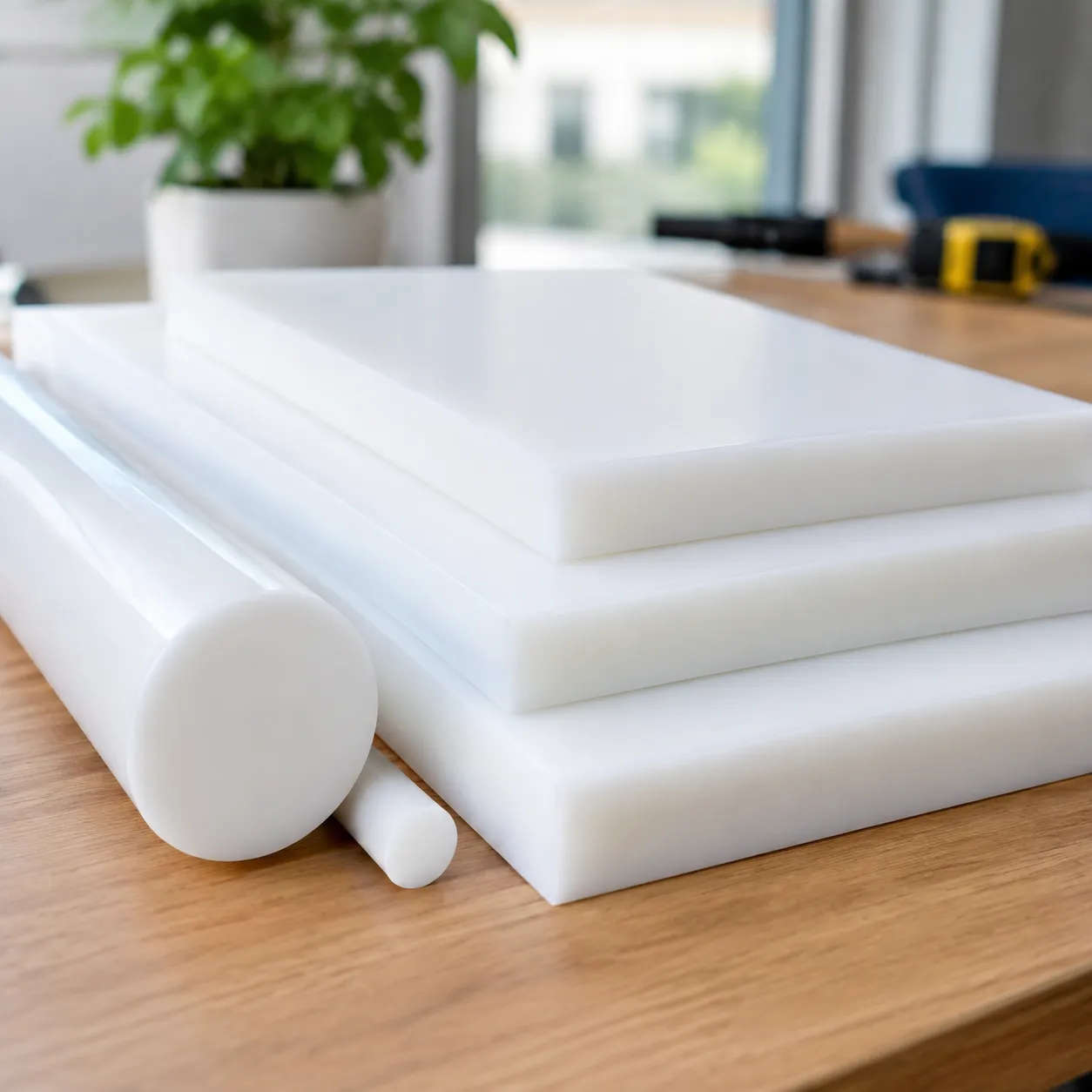
Made to order: this page describes a custom machining service. The product image is an AI-generated concept illustration, not a photograph of a supplied part or a production drawing. Dimensions, material grade and machine compatibility must be defined in the approved customer drawing.
Machining Scope for Pusher Blocks and Infeed Components
We can review drawing-defined stepped blocks, product-contact profiles, mounting holes, counterbores, threads, locating slots and related brackets. Supply an assembly reference where the relationship between the working face and mounting plane is critical. Left-hand and right-hand versions should have separate part identifiers or an explicit controlled instruction.
The concept shown illustrates a stepped block with a raised contact face and counterbored mounting flange. It is a visual example of a machinable form; your part may have a different profile, hole pattern or mounting arrangement. We manufacture against the released drawing rather than copying illustration proportions.
Material Options: Confirm the Exact Grade
| Material family | Information required for quotation |
|---|---|
| POM / acetal | Grade, color if required, working temperature, contact and cleaning requirements. |
| UHMW-PE | Grade, dimensions, supported sections and the drawing tolerances for the actual part. |
| PEEK | Unfilled or specified filled grade, operating conditions and critical interfaces. |
| Aluminum or stainless steel | Alloy, finish or treatment, mating requirements and any specified material documentation. |
Material selection belongs to the machine designer or equipment owner. Color alone does not establish material identity or food-contact compliance. Where applicable, request documentation for the specific material grade and intended use. Metal and plastic versions require separate engineering review.
Drawing Features That Control Fit
- Working face: show the contact profile, travel direction, working height and edge requirements.
- Mounting references: define the seating face and any locating feature used to position the block.
- Hole pattern: specify positions, sizes, thread/depth and counterbore details from controlled references.
- Mating clearance: provide the approved assembly envelope and clearance requirements.
- Revision control: use matching part numbers and revisions on the PDF and STEP files.
For a detailed preparation guide, read Flow Wrapper Pusher Blocks: Mating Interfaces and Replacement Drawings. Worn sample measurements should be recorded separately from approved nominal dimensions.
Tolerances and Inspection
Final tolerances are reviewed against material, size, geometry, machining access, finish and inspection requirements. For metal components, typical machining capability is ±0.01 mm, with selected dimensions down to ±0.005 mm after technical review. These figures are not a blanket specification for plastic pusher blocks. Confirm the acceptance limits for every critical feature before production.
Agree the inspection plan at quotation: part identification, mounting-hole positions, seating references, working-face location and other drawing-marked characteristics. CMM inspection and material traceability requirements can be included in the technical review. Assembly fit and operation on the machine require the equipment owner's approval.
Samples and Repeat Batches
Send the sample quantity, quantity per version and expected repeat-batch requirement. Approve the drawing revision and first-article acceptance criteria before releasing the batch. Pricing and lead time depend on the actual drawing, material availability, finishing and order quantity; each project receives its own quotation.
Send a Drawing Package for Your RFQ
- 2D PDF and STEP files with part number and revision.
- Material grade, quantity per version and expected batch quantities.
- Critical dimensions, finishes, heat treatment if any and inspection documents required.
- Working orientation, relevant mating information and requested delivery date.
ZSCNC supports drawing-based B2B OEM orders from its Wuxi manufacturing operation, with Shanghai handling international business and export. Browse our flow wrapper custom CNC parts or submit your controlled drawing package for machining review.